P0748-MODULATOR PRESSURE SOLENOID CIRCUIT
For a complete wiring diagram, refer to the Wiring Information.
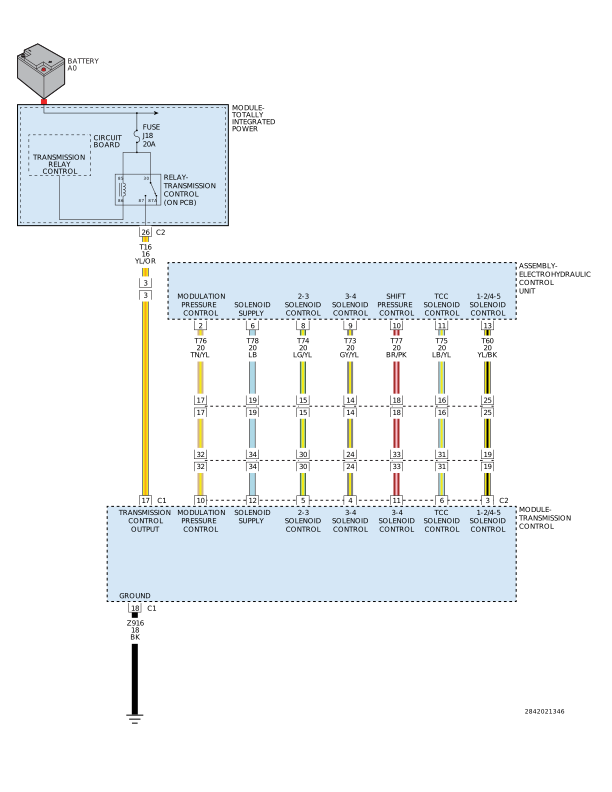 |
Theory of Operation
The Modulating Pressure Control Solenoid Valve's purpose is to control the modulating pressure depending on the continuously changing operating conditions, such as load and gear change.
The Modulating Pressure Control Solenoid Valve is always active. The solenoid uses pulse width modulation (PWM) to control the transmissions hydraulic fluid pressure that is determined by the Transmission Control Module (TCM).
-
When Monitored:
Continuously with the ignition on, engine running, the Modulating Pressure Control Solenoid Valve is either off, or active with 25-75% duty cycle, with no Solenoid Supply Voltage DTCs present.
-
Set Condition:
When the Modulating Pressure Control Solenoid Valve is commanded on and theTCM detects a solenoid circuit error (the measured current and target current does not match within a calibrated amount) or when the solenoid is commanded off and a short to ground is detected.
Possible Causes |
|---|
| (T76) MODULATION PRESSURE CONTROL CIRCUIT OPEN |
| (T76) MODULATION PRESSURE CONTROL CIRCUIT SHORTED TO GROUND |
| (T76) MODULATION PRESSURE CONTROL CIRCUIT SHORTED TO ANOTHER CIRCUIT |
| MODULATING PRESSURE CONTROL SOLENOID VALVE |
| TRANSMISSION CONTROL MODULE (TCM) |
Always perform the NAG1 Pre-Diagnostic Troubleshooting procedure before proceeding. (Refer to 28 - DTC-Based Diagnostics/MODULE, Transmission Control (TCM) - Standard Procedure).
1. CHECK IF THE DTC IS CURRENT
| NOTE: | When the Transmission Control Module (TCM) detects and stores a DTC, the TCM also stores the vehicles operating conditions under which the DTC originally set. This information is located in scan tool under Environmental Data. Before erasing any stored DTCs, record any available data to assist in duplicating the conditions in which the DTC originally set. |
| 1. | Turn the ignition off to the lock position. |
| 2. | With the scan tool, erase Transmission DTCs. |
| 3. | Using the Environmental Data recorded earlier, try to duplicate the conditions in which the DTC originally set. It may be necessary to test drive the vehicle. |
| 4. | With the scan tool, read Transmission DTCs. |
Did the DTC P0748 reset?
Yes
- Go To 2
No
- Go To 6
2. CHECK THE (T76) MODULATION PRESSURE CONTROL CIRCUIT FOR AN OPEN
| 1. | Turn the ignition off to the lock position. |
| 2. | Disconnect the TCM C2 harness connector. |
| 3. | Disconnect the Transmission Electrohydraulic Control Unit Assembly harness connector. |
| NOTE: | Check connectors - Clean/repair as necessary. |
| 4. | Measure the resistance of the (T76) Modulation Pressure Control circuit between the TCM C2 harness connector and the Transmission Electrohydraulic Control Unit Assembly harness connector. |
Is the resistance below 5.0 Ohms?
Yes
- Repair the (T76) Modulation Pressure Control circuit for an open.
- Perform the TRANSMISSION VERIFICATION TEST. (Refer to 28 - DTC-Based Diagnostics/MODULE, Transmission Control (TCM) - Standard Procedure).
No
-
Go To 3
3. CHECK THE (T76) MODULATION PRESSURE CONTROL CIRCUIT FOR A SHORT TO GROUND
| 1. | Measure the resistance between ground and the (T76) Modulation Pressure Control circuit. |
Is the resistance below 5.0 Ohms?
Yes
- Repair the (T76) Modulation Pressure Control circuit for a short to ground.
- Perform the TRANSMISSION VERIFICATION TEST. (Refer to 28 - DTC-Based Diagnostics/MODULE, Transmission Control (TCM) - Standard Procedure).
No
-
Go To 4
4. CHECK THE (T76) MODULATION PRESSURE CONTROL CIRCUIT FOR A SHORT TO ANOTHER CIRCUIT
| 1. | Measure the resistance between the (T76) Modulation Pressure Control circuit and every other circuit in the Transmission Electrohydraulic Control Unit Assembly harness connector. |
Is the resistance below 5.0 Ohms?
Yes
- Repair the (T76) Modulation Pressure Control circuit for a short to another circuit.
- Perform the TRANSMISSION VERIFICATION TEST. (Refer to 28 - DTC-Based Diagnostics/MODULE, Transmission Control (TCM) - Standard Procedure).
No
-
Go To 5
5. CHECK THE MODULATING PRESSURE CONTROL SOLENOID VALVE
| 1. | Reconnect the Transmission Electrohydraulic Control Unit Assembly harness connector. |
| 2. | Measure the resistance between the (T76) Modulation Pressure Control circuit and the (T78) Solenoid Supply Voltage circuit in the TCM C2 harness connector. |
Is the resistance between 2.5 and 6.5 Ohms?
Yes
- Using the schematics as a guide, check the Transmission Control Module (TCM) terminals for corrosion, damage, or terminal push out. Pay particular attention to all power and ground circuits. If no problems are found, replace the TCM in accordance with the Service Information.
- Perform the TRANSMISSION VERIFICATION TEST. (Refer to 28 - DTC-Based Diagnostics/MODULE, Transmission Control (TCM) - Standard Procedure).
No
6. CHECK THE WIRING AND CONNECTORS
| 1. | The conditions necessary to set this DTC are not present at this time. |
| 2. | Using the schematics as a guide, inspect the wiring and connectors specific to this circuit. |
| 3. | Wiggle the wiring and connectors while checking for any possible open or shorted circuits. |
| 4. | Check for any Service Information Tune-ups or Technical Service Bulletins that may apply. |
Were there any problems found?
Yes
- Repair as necessary.
- Perform the TRANSMISSION VERIFICATION TEST. (Refer to 28 - DTC-Based Diagnostics/MODULE, Transmission Control (TCM) - Standard Procedure).
No