Home › 28 - DTC-Based Diagnostics › MODULE, Wireless Control (WCM) › B210A-SYSTEM VOLTAGE LOWB210A-SYSTEM VOLTAGE LOW
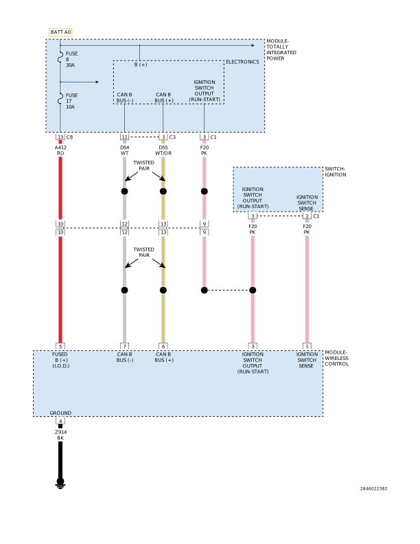
For a complete wiring diagram, refer to the Wiring Information .
Possible Causes
FUSED IGNITION SWITCH
OUTPUT (RUN-START) CIRCUIT OPEN
FUSED (B+) CIRCUIT
OPEN
WIRELESS CONTROL MODULE
(WCM)/SENTRY KEY REMOTE ENTRY MODULE (SKREEM)
1.
DETERMINING IF DIAGNOSTIC TROUBLE CODE (DTC) IS CURRENT
NOTE:
Diagnose any related Powertrain DTCs before continuing.
1.
With a scan tool, read and record DTCs.
2.
With the scan tool, clear DTCs.
3.
Perform 5 ignition cycles, leaving the ignition switch on for a minimum of 90 seconds per cycle.
4.
Using the scan tool, read DTCs.
Does the DTC reset? Yes
No
2.
INTERMITTENT CONDITION
NOTE:
Check for any of the follow conditions:
Poor wire to terminal connection
Corroded terminals
Backed out or loose terminals
Broken wire internal to the insulation
Dirty (partial) module ground
1.
With the ignition on, wiggle the related wires.
2.
Using a scan tool, read DTCs.
Does the DTC reset? Yes
No
3.
FUSED IGNITION SWITCH OUTPUT (RUN-START) CIRCUIT OPEN
NOTE:
Check the related fuses to the Fused Ignition Switch Output (Run-Start) circuit. If the fuse is found to be open repair the circuit for a shorted condition.
1.
Turn the ignition off.
2.
Disconnect the WCM harness connector.
4.
Using a 12 volt test light connected to ground, probe the Fused Ignition Switch Output (Run-Start) circuit in the WCM harness connector.
Does the test light illuminate brightly? Yes
No
4.
FUSED (B+) CIRCUIT OPEN
1.
Turn the ignition off.
2.
Using a 12 volt test light connected to ground, probe the Fused (B+) circuit in the WCM harness connector.
Does the test light illuminate brightly? Yes
No
5.
WCM
NOTE:
Repeat the below procedure for both the Fused Ignition Switch Output (Run-Start) circuit and the Fused (B+) circuit.
NOTE:
A dirty (partial) ground can cause abnormal conditions within a system. Ensure the module has a good ground before continuing.
1.
Turn the ignition off.
2.
Reconnect the WCM connector.
3.
Back probe the Fused Ignition Switch Output (Run-Start) circuit and then the Fused (B+) circuit.
5.
Using the scan tool, view battery voltage under Data Display in the Engine category.
6.
Compare the voltage on the scan tool to the voltage reading on the voltmeter.
Is the voltage on the scan tool equal to the voltmeter reading +/- .5 volt? Yes
No