P1605 IGNITION SWITCH
For a complete wiring diagram, refer to the Wiring Information.
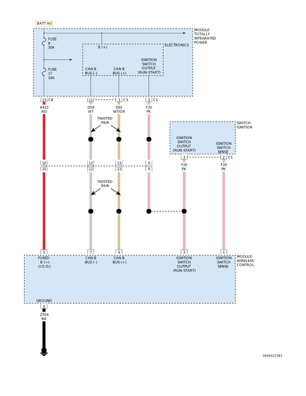 |
- When Monitored: Continuously with the Ignition switch on, the WCM monitors the G20 Ignition Switch Sense circuit .
- Set Conditions: If the Ignition Switch Sense Enabled shows “TRUE” and the action status in the Data Display screen shows SNA (Signal Not Available) for more than 5 seconds the fault will set as active.
Possible Causes |
|---|
| IGNITION SWITCH |
| (G20) IGNITION SWITCH SENSE CIRCUIT |
| WCM (WIRELESS CONTROL MODULE) |
| AFTERMARKET ADD ON EQUIPMENT |
Diagnostic Test
| NOTE: | A Mopar Accessory or Aftermarket add on remote start or remote start antenna failure can cause this fault code to be active. Remove/Disconnect it then recheck the concern. |
| 1. | Put the key in the ignition and turn the ignition on. |
| 2. | With the scan tool record all DTCs. |
Does the scan tool display this code as active?
Yes
- Go To 2
No
- The conditions that caused this code to set are not present at this time. Check for any related aftermarket equipment added on requiring an ignition type of feed and recheck for the concern.
- Perform the WCM VERIFICATION TEST. (Refer to 28 - DTC-Based Diagnostics/MODULE, Wireless Control (WCM) /Standard Procedure).
2. CHECKING THE IGNITION SWITCH SENSE STATUS.
| 1. | With the scan tool, check the Ignition_Sw_Sense_Enabled AND ActIgnStat on the data display screen for the WCM. |
Does the data display screen show Ignition_Sw_Sense_Enabled as TRUE; and does the ActIgnStat show “SNA” for longer than 5 seconds?
Yes
- Go To 3
No
- If the fault is presently Active, replace the WCM (Wireless Control Module) in accordance with Service Information. (Refer to 08 - Electrical/8Q - Vehicle Theft Security/MODULE, Sentry Key Immobilizer (SKREEM) /Removal).
3. CHECKING THE G20 IGNITION SWITCH SENSE CIRCUIT.
| NOTE: | The G20 circuit is a 5 volt sense circuit from the Ignition Switch to the WCM. |
| 1. | With the scan tool, monitor the ignition key switch position status. |
| 2. | Using a DVOM backprobe the G20 Ignition Switch Sense circuit at the WCM, and note the voltages for each position. |
| 3. | Compare the key position status to the approximate key position voltage: |
Does the key position status and approximate key position voltages match?
Yes
- Using the wiring diagram/schematic as a guide, inspect the wiring and connectors. Look for chaffed, pierced, pinched, or partially broken wires and broken, bent, pushed out, spread, corroded, or contaminated terminals.
- If no problem found with the wiring, terminals or connections, replace the WCM in accordance with Service Information. (Refer to 08 - Electrical/8Q - Vehicle Theft Security/MODULE, Sentry Key Immobilizer (SKREEM) /Removal).
No
- Using the wiring diagram/schematic as a guide, inspect the wiring and connectors. Look for chaffed, pierced, pinched, or partially broken wires and broken, bent, pushed out, spread, corroded, or contaminated terminals. Perform a voltage drop test on the G20 Ignition Switch Sense circuit.
- If there was no problem found with the wiring after inspection and there was no voltage drop on the G20 Ignition Switch Sense circuit when checked, replace the Ignition Switch in accordance with Service Information. (Refer to 19 - Steering/Column/SWITCH, Ignition/Removal) .