B142E-GPS ANTENNA NOT CONNECTED
Special Tools: Click to display a list of tools used in this procedure
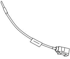
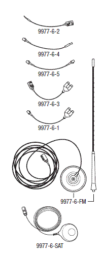
For a complete wiring diagram, Refer to the Wiring Information.
-
When Monitored:
With the ignition on and the Radio in Navigation mode.
-
Set Condition:
With the Radio in Navigation mode. The Radio does not detect an Antenna connection or does not receive a Navigation (GPS) signal.
Possible Causes |
|---|
| BAD ANTENNA CONNECTION |
| RADIO |
| ANTENNA |
1. CHECK THE ANTENNA CONNECTION
| 1. | Turn the ignition off. |
| 2. | Disconnect the Antenna connector at the back of the Radio. |
| 3. | Inspect the Antenna connections. |
Are the Antenna connections clean and secure?
Yes
- Go To 2
No
- Repair the Antenna connection as needed.
- Perform the BODY VERIFICATION TEST. (Refer to 28 - DTC-Based Diagnostics/MODULE, Totally Integrated Power (TIPM) - Standard Procedure).
2. CHECK THE ANTENNA AND CABLE
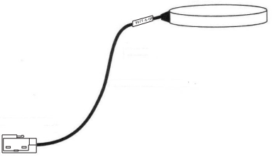
| 1. | Connect the 9977-6-GPS test antenna Adapter, GPS Antenna Diagnostic 9977-6-GPS to the antenna connection on the back of the Radio. |
| 2. | Make sure one of the front doors is still open. |
| 3. | Using the scan tool, erase the DTCs. |
| 4. | Turn the ignition on. |
| 5. | Turn the Radio on. |
| 6. | Using the scan tool, read the active Radio DTCs. |
| NOTE: | While using the 9977-6-GPS test antenna the Satellite radio reception will not be available and Satellite radio faults may occur. The 9977-6-GPS test tool will only enable GPS reception to work. For Satellite Radio reception concerns use test antenna 9977-6-SAT. |
Does the scan tool read: B142E-GPS ANTENNA NOT CONNECTED as active?
Yes
- Replace the Radio in accordance with the Service Information. (Refer to 08 - Electrical/8A - Audio and Video/RADIO/Removal) .
- Perform the BODY VERIFICATION TEST. (Refer to 28 - DTC-Based Diagnostics/MODULE, Totally Integrated Power (TIPM) - Standard Procedure).
No
- Go To 3
| 1. | Disconnect the Antenna cable at the base. |
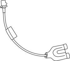
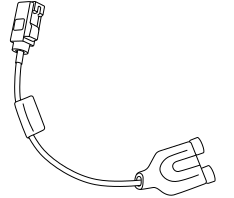
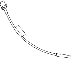
| 2. | Connect the appropriate Adapter 9977-6-1 or Adapter 9977-6-3 to the Antenna cable at the back of the Radio. |
| 3. | Connect the appropriate Jumper 9977-6-4 or Jumper 9977-6-2 to the Antenna cable at the Antenna base. |
| 4. | Measure the Resistance across the tool terminals. |
Is the resistance above 52.5 Ohms?
Yes
-
Use the
Kit, Radio Antenna Diagnostic 9977-6
to locate the open circuit, repair or replace the Antenna cable as necessary. - Perform the BODY VERIFICATION TEST. (Refer to 28 - DTC-Based Diagnostics/MODULE, Totally Integrated Power (TIPM) - Standard Procedure).
No
- Replace the Antenna base in accordance with the Service Information.
- Perform the BODY VERIFICATION TEST. (Refer to 28 - DTC-Based Diagnostics/MODULE, Totally Integrated Power (TIPM) - Standard Procedure).