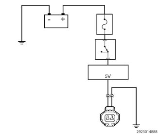
Check the 5-volt supply
circuit for an open or short to ground. For further assistance, perform
the appropriate Sensor Reference Voltage DTC diagnostic procedure.
2.
TESTING A 5-VOLT
SUPPLY CIRCUIT AND SENSOR GROUND CIRCUIT
1.
With the multimeter
set to measure DC voltage.
2.
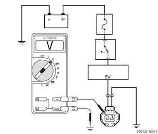
Move the negative
lead of the multimeter to carefully probe the sensor ground or sensor
return circuit in the harness connector.
3.
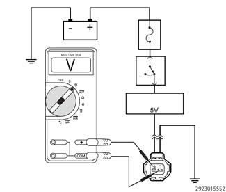
With the positive
lead of the multimeter, carefully probe the 5-volt supply circuit.
Is the
voltage between 4.7 and 5.2 volts?
Yes
At this time the 5-volt
supply and sensor ground circuit are working properly. Continue to
measure the voltage between the wires, wiggle the wire harness and
connectors while checking for an intermittent condition.
Use the wiring diagram
as a guide to trace the circuits and look for any in-line connectors
where the open could occur intermittently.
Look for any chafed,
pierced, pinched, or partially broken wires.
Look for broken, bent,
pushed out or corroded terminals. Verify that there is good pin to
terminal contact in the related wire harness connectors.
Perform any Technical
Service Bulletins (TSBs) that may apply.
No
Repair the open or
excessive resistance in the Sensor Ground (Sensor Return) circuit.