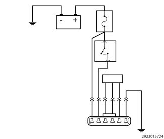
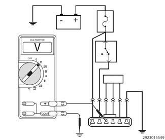
The purpose of the following procedure is to demonstrate different
methods of checking for a short to voltage in a circuit. When diagnosing
a DTC it might be necessary to verify that proper voltage is on a
circuit or that a circuit is not shorted high.
NOTE:
The circuit shown
is an example, and is intended for demonstrational purpose only.
The following are circuit tests covered in this procedure:
Testing For A Short
To Battery Voltage Using A Voltmeter
Testing For A Short
To Switched Battery Voltage Using A Voltmeter
Testing For A Short
To Battery Voltage Using A 12-Volt Test Light
Testing For A Short
To Switched Battery Voltage Using A 12-Volt Test Light
NOTE:
Perform the
following test using a known good test light or functioning multimeter.
Below is a list of possible causes that could be related to a Short
To Voltage condition.
Possible Causes
SHORTED CIRCUIT (CHAFED, PIERCED OR PINCHED WIRES)
SHORTED IN-LINE CONNECTOR (BENT, PUSHED OUT OR
CORRODED TERMINALS)
1.
TESTING FOR
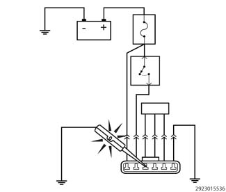
A SHORT TO BATTERY VOLTAGE USING A TEST LIGHT
NOTE:
Before testing any
circuits, first verify the 12-volt test light is operating properly.
Connect the 12-volt test light to battery ground or to any other known
good ground. Touch the lead of the test light to Battery(+). If the
test light is operational, it should illuminate brightly.
1.
Turn the ignition
off.
2.
Disconnect the
wire harness connectors of all components that contain the circuits
that are suspected of having the short.
NOTE:
Check connectors -
Clean/repair as necessary.
3.
At this time leave
all in-line connectors connected.
4.
Connect the 12-volt
test light to a known good ground.
5.
Use the lead of
the test light and carefully probe the circuit suspected of having
the short.
WARNING:
When the engine is operating, do
not stand in direct line with the fan. Do not put your hands near
the pulleys, belts or fan. Do not wear loose clothing. Failure to
follow these instructions may result in possible serious or fatal
injury.
6.
First, check with
the ignition off , next with the ignition on, and lastly while cranking
the engine.
Does
the test light illuminate brightly?
Yes
Repair the short to
voltage. Use the wiring diagram as a guide to trace the circuits and
look for any in-line connectors where the short could occur.
One method to help
isolate the short is to disconnect any in-line connectors that the
circuit being checked runs through and check for the short again.
If the short goes away, the short is on the other side of the in-line
connector.
No
The circuit is not
shorted to voltage or the condition that originally caused the short
may not be present at this time. Continue to measure the resistance
and wiggle the wire harness to check for an intermittent short.
NOTE:
By disconnecting
the wire harness connectors you may have eliminated the source of
the voltage causing the short. Use the wiring diagram as a guide,
check to see if there are any battery circuits in the same wire harness
as the circuit you are testing. It is necessary to check for a short
to those circuits using an ohmmeter. (Refer to 29 - Non-DTC Diagnostics/Circuit
Testing Procedures - Standard Procedure)
and perform the Check
for a Short Between Multiple Circuits diagnostic procedure.
Use the wiring diagram
as a guide to trace the circuits and look for any in-line connectors
where the short could occur intermittently.
Look for any chafed,
pierced, pinched, or partially broken wires.
Look for broken, bent,
pushed out or corroded terminals. Verify that there is good pin to
terminal contact in the related component and wire harness connectors.
Perform any Technical
Service Bulletins (TSBs) that may apply.
2.
TESTING FOR
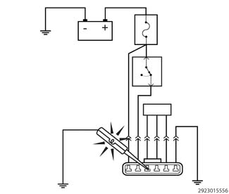
A SHORT TO SWITCHED IGNITION VOLTAGE USING A TEST LIGHT
NOTE:
Before testing any
circuits, first verify the 12-volt test light is operating properly.
Connect the 12-volt test light to battery ground or to any other known
good ground. Touch the lead of the test light to Battery(+). If the
test light is operational, it should illuminate brightly.
1.
Turn the ignition
off.
2.
Disconnect the
wire harness connectors of all components that contain the circuits
that are suspected of having the short.
NOTE:
Check connectors -
Clean/repair as necessary.
3.
At this time leave
all in-line connectors connected.
4.
Connect the 12-volt
test light to a known good ground.
5.
Use the lead of
the test light and carefully probe the circuit suspected of having
the short.
WARNING:
When the engine is operating, do
not stand in direct line with the fan. Do not put your hands near
the pulleys, belts or fan. Do not wear loose clothing. Failure to
follow these instructions may result in possible serious or fatal
injury.
6.
First, check with
the ignition off , next with the ignition on, and lastly while cranking
the engine.
Does
the test light illuminate brightly?
Yes
Repair the short to
voltage. Use the wiring diagram as a guide to trace the circuits and
look for any in-line connectors where the short could occur.
One method to help
isolate the short is to disconnect any in-line connectors that the
circuit being checked runs through and check for the short again.
If the short goes away, the short is on the other side of the in-line
connector.
No
The circuit is not
shorted to voltage or the condition that originally caused the short
may not be present at this time. Continue to measure the resistance
and wiggle the wire harness to check for an intermittent short.
NOTE:
By disconnecting
the wire harness connectors you may have eliminated the source of
the voltage causing the short. Use the wiring diagram as a guide,
check to see if there are any battery circuits in the same wire harness
as the circuit you are testing. It is necessary to check for a short
to those circuits using an ohmmeter. (Refer to 29 - Non-DTC Diagnostics/Circuit
Testing Procedures - Standard Procedure)
and perform the Check
for a Short Between Multiple Circuits diagnostic procedure.
Use the wiring diagram
as a guide to trace the circuits and look for any in-line connectors
where the short could occur intermittently.
Look for any chafed,
pierced, pinched, or partially broken wires.
Look for broken, bent,
pushed out or corroded terminals. Verify that there is good pin to
terminal contact in the related component and wire harness connectors.
Perform any Technical
Service Bulletins (TSBs) that may apply.
3.
TESTING FOR
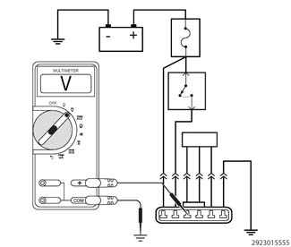
A SHORT TO BATTERY VOLTAGE USING A VOLTMETER
1.
Turn the ignition
off.
2.
Disconnect the
wire harness connectors of the components that contain the circuit
that is suspected as having a short.
NOTE:
Check connectors -
Clean/repair as necessary.
3.
At this time leave
all in-line connectors connected.
4.
With all the component
wire harness connectors disconnected, use a multimeter set to measure
DC voltage.
5.
Connect the ground
lead of the meter to a known good ground.
6.
Use the positive
lead of the multimeter and probe the circuit that is being checked
for a short.
Is there
any voltage present?
Yes
Repair the short to
battery voltage. Use the wiring diagram as a guide to trace the circuits
and look for any in-line connectors where the short could occur.
One method to help
isolate the short is to disconnect any in-line connectors that the
circuit being checked runs through and measure for the short again.
If the short goes away, the short is on the other side of the in-line
connector.
No
The circuit is not
shorted to voltage or the condition that originally caused the short
may not be present at this time. Continue to measure the voltage and
wiggle the wire harness to check for an intermittent short.
NOTE:
By disconnecting the
wire harness connectors you may have eliminated the source of the
voltage causing the short. Use the wiring diagram as a guide, check
to see if there are any battery circuits in the same wire harness
as the circuit you are testing. It is necessary to check for a short
to those circuits using an ohmmeter. (Refer to 29 - Non-DTC Diagnostics/Circuit
Testing Procedures - Standard Procedure)
and perform the Check
for a Short Between Multiple Circuits diagnostic procedure.
Use the wiring diagram
as a guide to trace the circuits and look for any in-line connectors
where the short could occur intermittently.
Look for any chafed,
pierced, pinched, or partially broken wires.
Look for broken, bent,
pushed out or corroded terminals. Verify that there is good pin to
terminal contact in the related wire harness connectors.
Perform any Technical
Service Bulletins (TSBs) that may apply.
4.
TESTING FOR
A SHORT TO SWITCHED IGNITION VOLTAGE USING A VOLTMETER
1.
Turn the ignition
off.
2.
Disconnect the
wire harness connectors of all components that contain the circuits
that are suspected as being shorted.
NOTE:
Check connectors -
Clean/repair as necessary.
3.
At this time leave
all in-line connectors connected.
4.
With all the component
wire harness connectors disconnected, use a multimeter set to measure
DC voltage.
5.
Connect the ground
lead of the meter to a known good ground.
6.
Use the positive
lead of the multimeter and probe the circuit suspected of having the
short.
7.
Ignition on, engine
not running.
Is any
voltage present?
Yes
Repair the short to
ignition voltage. Use the wiring diagram as a guide to trace the circuits
and look for any in-line connectors where the short could occur.
One method to help
isolate the short is to disconnect any in-line connectors that the
circuit being checked runs through and check for the short again.
If the short goes away, the short is on the other side of the in-line
connector.
No
The circuit is not
shorted to voltage or the condition that originally caused the short
may not be present at this time. Continue to measure the voltage and
wiggle the wire harness to check for an intermittent short.
NOTE:
By disconnecting the
wire harness connectors you may have eliminated the source of the
voltage causing the short. Use the wiring diagram as a guide, check
to see if there are any battery circuits in the same wire harness
as the circuit you are testing. It is necessary to check for a short
to those circuits using an ohmmeter. (Refer to 29 - Non-DTC Diagnostics/Circuit
Testing Procedures - Standard Procedure)
and perform the Check
for a Short Between Multiple Circuits diagnostic procedure.
Use the wiring diagram
as a guide to trace the circuits and look for any in-line connectors
where the short could occur intermittently.
Look for any chafed,
pierced, pinched, or partially broken wires.
Look for broken, bent,
pushed out or corroded terminals. Verify that there is good pin to
terminal contact in the related wire harness connectors.
Perform any Technical
Service Bulletins (TSBs) that may apply.