A circuit load test can be performed to test the ability of a circuit
to carry the current required to operate a connected device. A circuit
load test should be performed after a circuit has passed a resistance
test using a DVOM and the circuit is still suspected of a failure.
A single copper
wire strand will carry enough current to light a test light bulb,
while showing very low resistance using a DVOM.
Some test lights
are insufficient for load testing because of the very low resistance
bulb being used.
The Load Test tool
listed below will require higher current flow to power the bulb; and
this will test the ability of the circuit to carry a load.
This test will
indicate if the circuit being tested can carry the current required
to operate a connected device.
WARNING:
To avoid possible serious or fatal injury,
DO NOT load test any air bag/restraint system components or circuits
using the procedures listed here. Refer to the Service Information
for proper air bag/restraint system testing procedures.
CAUTION:
Do not load test any circuits with components still connected
to the circuit.
NOTE:
Depending upon
the location of the circuit in question, this test may require jumper
wires.
NOTE:
Use the wiring
diagrams as a guide to trace the circuits and look for any in-line
connectors where the circuit failure could occur intermittently. Look
for any chafed, pierced, pinched, or partially broken wires. Look
for broken, bent, pushed out or corroded terminals - clean/repair
as necessary. Verify that there is good pin to terminal contact in
the related wire harness connectors.
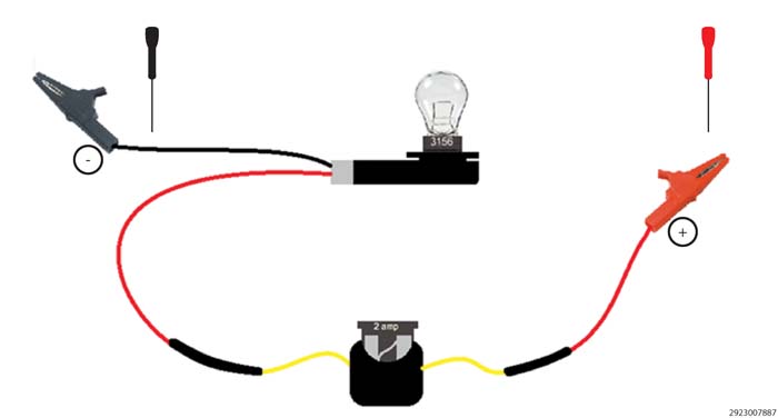
Here is an example of a simple tool you can build to test a circuit`s
ability to carry a load.
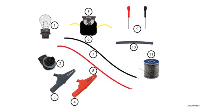
The following is a list of components required to build a load
test tool:
3156 Bulb
3156 Bulb socket
Negative alligator
clip with covers
Positive alligator
clip with covers
2 Amp mini fuse
Mini fuse holder
2’ to 4’ of Black
16ga wire
2’ to 4’ of Red
16ga wire
Approved back probe
tool
Shrink tubing
Solder
LOAD TESTING
A GROUND CIRCUIT
DIAGNOSTIC LOAD
TEST (GROUND CIRCUIT)
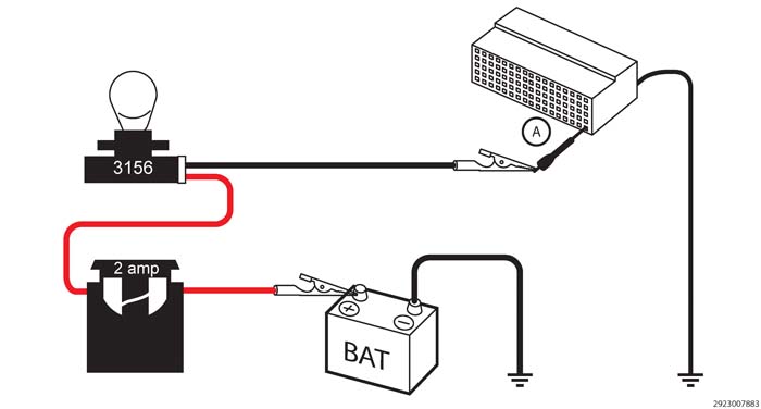
1.
Disconnect the
connector from the device(s) to gain access and isolate the terminal
for the circuit being tested.
2.
Connect the positive
lead of the load test tool to the positive side of the battery.
3.
Using an approved
connector back probe tool, connect the negative lead of the load test
tool to the circuit being tested at point (A).
CAUTION:
Use only approved connector back
probe tools when back probing a connector so as not to cause damage
to the terminals or insulation of the connector. Damage to the terminals
can cause poor terminal contact or retention. Damage to the insulation
can introduce corrosion due to water infiltration.
Does
the bulb light bright, when compared to a direct battery connection?
Yes
The circuit being tested
can carry a load, check other circuits, connectors and terminals for
concerns.
No
Repair the circuit,
connector or terminal that has an open or excessive resistance.
Perform any related
Recalls or Technical Service Bulletins (TSBs) that may apply.
LOAD TESTING
A BATTERY OR IGNITION FEED CIRCUIT
DIAGNOSTIC LOAD
TEST (BATTERY/IGNITION FEED CIRCUIT)
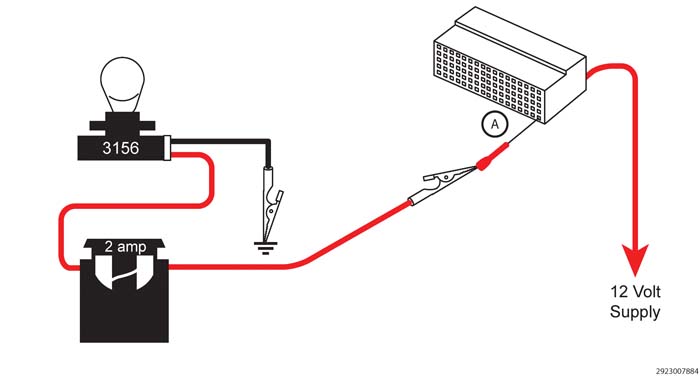
1.
Disconnect the
connector from the device(s) to gain access and isolate the terminal
for the circuit being tested.
2.
Using an approved
connector back probe tool, connect the positive lead of the load test
tool to the circuit being tested at point (A).
3.
Connect the negative
lead of the load test tool to the negative side of the battery or
ground.
CAUTION:
Use only approved connector back
probe tools when back probing a connector so as not to cause damage
to the terminals or insulation of the connector. Damage to the terminals
can cause poor terminal contact or retention. Damage to the insulation
can introduce corrosion due to water infiltration.
Does
the bulb light bright, when compared to a direct battery connection?
Yes
The circuit being tested
can carry a load, check other circuits, connectors and terminals for
concerns.
No
Repair the circuit,
connector or terminal that has an open or excessive resistance.
Perform any related
Recalls or Technical Service Bulletins (TSBs) that may apply.
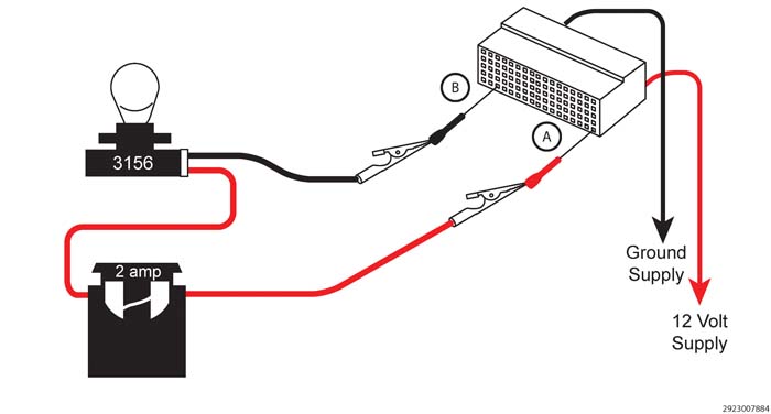
LOAD TESTING
A BATTERY OR IGNITION FEED CIRCUIT AND GROUND CIRCUIT
DIAGNOSTIC LOAD
TEST (BATTERY FEED & GROUND CIRCUIT)
1.
Disconnect the
connector from the device(s) to gain access and isolate the terminal
for the circuit being tested.
2.
Using an approved
connector back probe tool, connect the positive lead of the load test
tool to the circuit being tested at point (A).
3.
Using an approved
connector back probe tool, connect the negative lead of the load test
tool to the circuit being tested at point (B).
CAUTION:
Use only approved connector back
probe tools when back probing a connector so as not to cause damage
to the terminals or insulation of the connector. Damage to the terminals
can cause poor terminal contact or retention. Damage to the insulation
can introduce corrosion due to water infiltration.
Does
the bulb light bright, when compared to a direct battery connection?
Yes
The circuit being tested
can carry a load, check other circuits, connectors and terminals for
concerns.
No
Test the circuits individually
to determine which circuit is the cause of the test failure.
Repair the circuit,
connector or terminal that has an open or excessive resistance.
Perform any related
Recalls or Technical Service Bulletins (TSBs) that may apply.
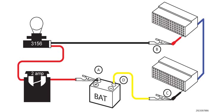
LOAD TESTING
A CIRCUIT FOR AN OPEN OR HIGH RESISTANCE
DIAGNOSTIC LOAD
TEST (OPEN/HIGH RESISTANCE CIRCUIT)
1.
Disconnect all
components from the circuit being tested.
2.
Connect the positive
lead of the load test tool to the positive side of the battery (A).
3.
Using an approved
connector back probe tool, connect the negative lead of the load test
tool to the circuit being tested at point (B).
4.
Using an approved
connector back probe tool, connect a jumper wire to the circuit being
tested at point (C).
5.
Then connect the
other end of the jumper wire to the negative side of the battery or
ground (D).
CAUTION:
Use only approved connector back
probe tools when back probing a connector so as not to cause damage
to the terminals or insulation of the connector. Damage to the terminals
can cause poor terminal contact or retention. Damage to the insulation
can introduce corrosion due to water infiltration.
Does
the bulb light bright, when compared to a direct battery connection?
Yes
The circuit being tested
can carry a load, check other circuits, connectors and terminals for
concerns.
No
Repair the circuit,
connector or terminal that has an open or excessive resistance.
Perform any related
Recalls or Technical Service Bulletins (TSBs) that may apply.