HVAC
- A/C CLUTCH COIL
- DIAGNOSIS AND TESTING - IN-CAR TEMPERATURE SENSOR
- POSITIVE TEMPERATURE COEFFICIENT (PTC) HEATER UNIT
A/C CLUTCH COIL

The A/C clutch coil electrical circuit is controlled by the Powertrain Control Module (PCM) through the A/C clutch relay. The A/C clutch coil can be tested by either measuring A/C clutch coil resistance or current draw. Begin testing of a suspected A/C clutch coil problem by performing the preliminary checks.
24-0007-00001-03-PRELIMINARY-CHECKS
A/C CLUTCH COIL SPECIFICATIONS
|
A/C Compressor |
Coil Resistance |
Current Draw |
|---|---|---|
|
Zexel DKS-17DS |
4.0 - 4.4 ohms |
3.3 amps Max @ 11.5 - 12.5 volts |
|
Visteon RS-18 |
3.0 - 4.0 ohms |
4.0 amps Max @ 11.5 - 12.5 volts |
PRELIMINARY CHECKS
- If the A/C clutch will not engage, check for Diagnostic Trouble Codes (DTCs) in the A/C heater control, Cabin Compartment Node (CCN) or the PCM. If no DTCs are found, go to Step 2. If any DTCs are found, repair as required.
- If the A/C clutch still will not engage, verify the refrigerant charge level by conducting the A/C Performance Test (Refer to 24 - Heating and Air Conditioning - Diagnosis and Testing) . If the refrigerant charge is OK, go to COIL RESISTANCE TEST and/or COIL CURRENT DRAW TEST. If the refrigerant charge is not OK, adjust the refrigerant charge as required.
COIL RESISTANCE TEST
- Disconnect and isolate the negative battery cable.
- Disconnect the wire harness connector from the A/C clutch coil connector.
- Use an ohmmeter and Back Probe Tool 6801 and measure the resistance of the A/C clutch coil at the coil connector terminals.
- See the A/C Clutch Coil Specifications chart for the acceptable A/C clutch coil resistance. Specifications apply for a work area temperature of 21° C (70° F).
COIL CURRENT DRAW TEST
- Verify the battery state of charge (Refer to 08 - Electrical/8F - Engine Systems/Battery System/BATTERY - Diagnosis and Testing) .
- Connect an ammeter (0 to 10 ampere scale selected) in series with the A/C clutch coil feed terminal using Back Probe Tool 6801 . Connect a voltmeter (0 to 20 volt scale selected) to measure voltage across the battery and the A/C clutch coil.
- With the A/C heater control in the A/C mode and the blower motor at low speed, start the engine and allow it to run at a normal idle speed.
- The A/C clutch should engage immediately and the clutch coil supply voltage should be within two volts of the battery voltage. If the A/C clutch coil supply voltage is OK, go to Step #5. If the A/C clutch coil supply voltage is not within two volts of battery voltage, test the A/C clutch coil feed circuit for excessive voltage drop and repair as necessary.
- See the A/C Clutch Coil Specifications chart for the acceptable A/C clutch coil current draw. Specifications apply for a work area temperature of 21° C (70° F). If voltage is more than 12.5 volts, add electrical loads by turning on electrical accessories until voltage reads below 12.5 volts.
DIAGNOSIS AND TESTING - IN-CAR TEMPERATURE SENSOR
| NOTE: |
For complete circuit diagrams, see Wiring Information. Wiring Information includes wiring diagrams, connector pin-out and location views, details of wire harness routing and retention, splice and ground locations and proper wire and connector repair procedures. |
Using a scan tool, check for Diagnostic Trouble Codes (DTCs) related to the in-car temperature sensor and the A/C-heater control. If any DTCs are found, repair as necessary (Refer to 28 - DTC-Based Diagnostics/HVAC - Diagnosis and Testing) . If no DTCs are found, perform the two following tests. Replace the in-car temperature sensor if the sensor fails either test.
- Remove the in-car temperature sensor and place it on a workbench (Refer to 24 - Heating and Air Conditioning/Controls/SENSOR, Temperature - Removal) .
- Note the current ambient air temperature of the work area.
- Use an ohm meter and check the resistance between pins 1 and 2 of the in-car temperature sensor. Compare the temperature of the work area to the found resistance value. The resistance should be within specifications as listed in the Resistance and Temperature chart. If not OK, replace the in-car temperature sensor.
RESISTANCE AND TEMPERATURE
|
Air Temperature Range |
Low Resistance Range (kohm) |
High Resistance Range (kohm) |
|---|---|---|
|
-21° to -15°C (-5° to 5°F) |
292 ± 1.0 |
223 ± 0.9 |
|
-14° to -9°C (6° to 15°F) |
198 ± 0.9 |
161 ± 0.8 |
|
-8° to -4°C (16° to 25°F) |
144 ± 0.8 |
123 ± 0.8 |
|
-3° to 1°C (26° to 35°F) |
111 ± 0.7 |
95 ± 0.7 |
|
2 to 7°C (36° to 45°F) |
86 ± 0.7 |
70 ± 0.6 |
|
8 to 12°C (46° to 55°F) |
64 ± 0.6 |
55 ± 0.5 |
|
13° to 18°C (56° to 65°F) |
51 ± 0.5 |
42 ± 0.4 |
|
19° to 23°C (66° to 75°F) |
39 ± 0.4 |
33 ± 0.3 |
|
24° to 29°C (76° to 85°F) |
31 ± 0.3 |
26 ± 0.3 |
|
30° to 35°C (86° to 95°F) |
24 ± 0.3 |
20 ± 0.3 |
|
36° to 40°C (96° to 105°F) |
18 ± 0.3 |
16 ± 0.3 |
|
41° to 46°C (106° to 115°F) |
15 ± 0.3 |
13 ± 0.3 |
ASPIRATOR MOTOR TEST
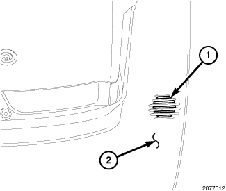
The in-car temperature sensor uses an aspirator motor to draw air from the passenger compartment and flow it over the temperature thermistor. Test the motor as follows.
 |
- Turn the ignition switch to Run position.
- Place a small piece of newspaper in front of the aspirator motor opening grille (1), located on the steering column opening cover (2). If the paper sticks to the grille, the aspirator motor is operating properly. The piece of paper should be only large enough to cover the opening.
-
If the paper does not stick to the grille, check the in-car temperature sensor electrical connections and wiring. If connections and wiring are OK, replace the in-car temperature sensor.
TEMPERATURE THERMISTOR TEST
The in-car temperature sensor uses a temperature thermistor to provide resistance values that correlate with temperature change. Test the thermistor as follows.
POSITIVE TEMPERATURE COEFFICIENT (PTC) HEATER UNIT
Disable the airbag system before
attempting any steering wheel, steering column or instrument panel
component diagnosis or service. Disconnect and isolate the negative
battery (ground) cable, then wait two minutes for the airbag system
capacitor to discharge before performing further diagnosis or service.
This is the only sure way to disable the airbag system. Failure to
follow these instructions may result in accidental airbag deployment
and possible serious or fatal injury.
WARNING:
| NOTE: |
See Wiring Information for circuit descriptions and diagrams. Wiring Information includes wiring diagrams, proper wire and connector repair procedures, further details on wire harness routing and retention as well as pin-out and location views for the various wire harness connectors, splices and grounds. |
Prior to replacing the Positive Temperature Coefficient (PTC) heater unit, check for any Diagnostic Trouble Codes (DTCs) related to the Powertrain Control Module (PCM), Totally Integrated Power Module (TIPM) and the heating and A/C system. Repair as necessary.
- Disconnect and isolate the negative battery cable.
- Disconnect the wire harness connector from the PTC heater unit (Refer to 24 - Heating and Air Conditioning/Cabin Heater/UNIT, Heater - Removal) .
- Using an ohmmeter, check for continuity between all of the PTC heater unit terminals. In each case there should be continuity. If OK, repair the wire harness circuits between the PTC heater unit and the TIPM. If NOT OK, replace the PTC heater unit.