Battery System
GR8 ELECTRICAL SYSTEM TESTER
The Midtronics GR8 battery system tester is designed to help diagnose the cause of a defective battery. (Refer to 08 - Electrical/8F - Engine Systems/Battery System/BATTERY - Standard Procedure) for directions on using the Midtronics GR8 battery tester.
DIAGNOSIS AND TESTING - BATTERY SYSTEM
The battery, starting, and charging systems in the vehicle operate with one another and must be tested as a complete system. In order for the engine to start and the battery to maintain its charge properly, all of the components that are used in these systems must perform within specifications. It is important that the battery, starting, and charging systems be thoroughly tested and inspected any time a battery needs to be charged or replaced. The cause of abnormal battery discharge, overcharging or early battery failure must be diagnosed and corrected before a battery is replaced and before a vehicle is returned to service. The service information for these systems has been separated within this service manual to make it easier to locate the specific information you are seeking. However, when attempting to diagnose any of these systems, it is important that you keep their interdependency in mind.
The diagnostic procedures used for the battery, starting, and charging systems include the most basic conventional diagnostic methods, to the more sophisticated On-Board Diagnostics (OBD) built into the Powertrain Control Module (PCM). Use of an induction-type milliampere ammeter, a volt/ohmmeter, a battery charger, a carbon pile rheostat (load tester) and a 12-volt test lamp may be required. All OBD-sensed systems are monitored by the PCM. Each monitored circuit is assigned a Diagnostic Trouble Code (DTC). The PCM will store a DTC in electronic memory for any failure it detects. (Refer to 08 - Electrical/8F - Engine Systems/Charging - Diagnosis and Testing) for the proper charging system on-board diagnostic test procedures.
|
BATTERY SYSTEM DIAGNOSIS |
||
|---|---|---|
|
CONDITION |
POSSIBLE CAUSES |
CORRECTION |
|
THE BATTERY SEEMS WEAK OR DEAD WHEN ATTEMPTING TO START THE ENGINE. |
1. The electrical system ignition-off draw is excessive. |
1. (Refer to 08 - Electrical/8F - Engine Systems/Battery System/BATTERY - Standard Procedure) for the proper test procedures. Repair the excessive ignition-off draw, as required. |
|
2. The charging system is inoperative. |
2. Determine if the charging system is performing to specifications, (Refer to 08 - Electrical/8F - Engine Systems/Charging - Diagnosis and Testing) . Repair the inoperative charging system, as required. |
|
|
3. The battery is discharged. |
3. Determine the battery state-of-charge using the Midtronics GR8 battery tester, (Refer to 08 - Electrical/8F - Engine Systems/Battery System/BATTERY - Standard Procedure) . Charge the battery as required. |
|
|
4. The battery terminal connections are loose or corroded. |
4. (Refer to 08 - Electrical/8F - Engine Systems/Battery System/CABLES, Battery - Diagnosis and Testing) . Clean and tighten the battery terminal connections, as required. |
|
|
5. The battery has an incorrect size or rating for this vehicle. |
5. (Refer to 08 - Electrical/8F - Engine Systems/Battery System - Specifications) for the proper size and rating. Replace an incorrect battery, as required. |
|
|
6. The battery is inoperative. |
6. Determine the battery cranking capacity using the Midtronics GR8 battery tester, (Refer to 08 - Electrical/8F - Engine Systems/Battery System/BATTERY - Standard Procedure) . Replace the inoperative battery, as required. |
|
|
7. The starting system is inoperative. |
7. Determine if the starting system is performing to specifications, (Refer to 08 - Electrical/8F - Engine Systems/Starting - Diagnosis and Testing) . Repair the inoperative starting system, as required. |
|
|
8. The battery is physically damaged. |
8. Inspect the battery for loose terminal posts or a cracked and leaking case. Replace the damaged battery, as required. |
|
|
THE BATTERY STATE OF CHARGE CANNOT BE MAINTAINED. |
1. The battery has an incorrect size or rating for this vehicle. |
1. (Refer to 08 - Electrical/8F - Engine Systems/Battery System - Specifications) for the proper size and rating. Replace an incorrect battery, as required. |
|
2. The battery terminal connections are loose or corroded. |
2. (Refer to 08 - Electrical/8F - Engine Systems/Battery System/CABLES, Battery - Diagnosis and Testing) . Clean and tighten the battery terminal connections, as required. |
|
|
3. The electrical system ignition-off draw is excessive. |
3. (Refer to 08 - Electrical/8F - Engine Systems/Battery System/BATTERY - Standard Procedure) for the proper test procedures. Repair the inoperative electrical system, as required. |
|
|
4. The battery is inoperative. |
4. Test the battery using the Midtronics GR8 battery tester, (Refer to 08 - Electrical/8F - Engine Systems/Battery System/BATTERY - Standard Procedure) . Replace the inoperative battery, as required. |
|
|
5. The starting system is inoperative. |
5. Determine if the starting system is performing to specifications, (Refer to 08 - Electrical/8F - Engine Systems/Starting - Diagnosis and Testing) . Repair the inoperative starting system, as required. |
|
|
6. The charging system is inoperative. |
6. Determine if the charging system is performing to specifications, (Refer to 08 - Electrical/8F - Engine Systems/Charging - Diagnosis and Testing) . Repair the inoperative charging system, as required. |
|
|
7. Electrical loads exceed the output of the charging system. |
7. Inspect the vehicle for aftermarket electrical equipment which might cause excessive electrical loads. |
|
|
8. Slow driving or prolonged idling with high-amperage draw systems in use. |
8. Advise the vehicle operator, as required. |
|
|
THE BATTERY WILL NOT ACCEPT A CHARGE. |
1. The battery is inoperative. |
1. Test the battery using the Midtronics GR8 battery tester, (Refer to 08 - Electrical/8F - Engine Systems/Battery System/BATTERY - Standard Procedure) . Replace the inoperative battery, as required. |
BATTERY
The battery Group Size number, the Cold Cranking Amperage (CCA) rating, and the Reserve Capacity (RC) rating or Ampere-Hours (AH) rating can be found on the original equipment battery label. Be certain that a replacement battery has the correct Group Size number, as well as CCA, and RC or AH ratings that equal or exceed the original equipment specification for the vehicle being serviced. Battery sizes and ratings are discussed in more detail below.
| NOTE: |
Vehicles equipped with a diesel engine utilize a unique battery. The specifications for this battery may differ from the standards shown here. Refer to the battery manufacturer for detailed specifications. |
- Group Size - The outside dimensions and terminal placement of the battery conform to standards established by the Battery Council International (BCI). Each battery is assigned a BCI Group Size number to help identify a correctly-sized replacement.
- Cold Cranking Amperage - The Cold Cranking Amperage (CCA) rating specifies how much current (in amperes) the battery can deliver for thirty seconds at -18° C (0° F). Terminal voltage must not fall below 7.2 volts during or after the thirty second discharge period. The CCA required is generally higher as engine displacement increases, depending also upon the starter current draw requirements.
- Reserve Capacity - The Reserve Capacity (RC) rating specifies the time (in minutes) it takes for battery terminal voltage to fall below 10.5 volts, at a discharge rate of 25 amperes. RC is determined with the battery fully-charged at 26.7° C (80° F). This rating estimates how long the battery might last after a charging system failure, under minimum electrical load.
- Ampere-Hours - The Ampere-Hours (AH) rating specifies the current (in amperes) that a battery can deliver steadily for twenty hours, with the voltage in the battery not falling below 10.5 volts. This rating is also sometimes identified as the twenty-hour discharge rating.
- Load Test Amperage - The Load Test Amperage rating specifies the current (in amperes) that a battery should be tested at with the battery load test equipment. This value should always be 50 percent of the CCA. For example: if the CCA for this battery is 700 amps, the Load Test Amperage is 50 percent of that or 350 amps.
|
BATTERY CLASSIFICATIONS AND RATINGS |
||||
|---|---|---|---|---|
|
BCI Group Size Classification |
Cold Cranking Amperage |
Reserve Capacity |
Ampere - Hours |
Load Test Amperage |
|
H6 |
600 |
120 Minutes |
70 |
300 |
|
H7/AGM (DIESEL) |
700 |
120 Minutes |
75 |
350 |
TORQUE
| DESCRIPTION | N·m |
Ft. Lbs. |
In. Lbs. |
|---|---|---|---|
|
Battery Terminal Clamp Pinch-Bolt Hex Nut |
5 |
- |
45 |
|
Battery Hold Down Bolt |
7 |
- |
62 |
|
Starter Solenoid B(+) Terminal Stud Nut |
13 |
- |
115 |
|
Battery Negative Cable Ground Eyelet Terminal To Engine Block Bolt |
16.5 |
- |
145 |
|
Generator Output Terminal Stud Nut |
14 |
- |
125 |
|
Totally Integrated Power Module B(+) Terminal Stud Nut |
10 |
- |
90 |
|
Battery Negative Cable Eyelet Terminal To The Inner Fender Bolt |
12 |
9 |
- |
|
Lower Battery Tray Bolts |
10.5 |
- |
93 |
|
Upper Battery Tray Bolts |
10.5 |
- |
93 |
|
Battery Tray Nut |
10.5 |
- |
93 |
CLEANING
The following information details the recommended cleaning procedures for the battery and related components. In addition to the maintenance schedules found in this service manual and the Owner's Manual, it is recommended that these procedures be performed any time the battery or related components must be removed for vehicle service.
 |
-
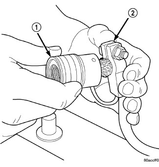
Clean the battery cable terminal clamps (2) of all corrosion. Remove any corrosion using a wire brush (1) or a post and terminal cleaning tool, and a sodium bicarbonate (baking soda) and warm water cleaning solution.
-
Clean the battery tray and battery holddown hardware of all corrosion. Remove any corrosion using a wire brush and a sodium bicarbonate (baking soda) and warm water cleaning solution. Paint any exposed bare metal.
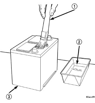
- If the removed battery is to be reinstalled, clean the outside of the battery case (3) and the top cover with a sodium bicarbonate (baking soda) and warm water cleaning solution using a stiff bristle parts cleaning brush (1) to remove any acid film. Rinse the battery with clean water. Ensure that the cleaning solution does not enter the battery cells through the vent holes. If the battery is being replaced, (Refer to 08 - Electrical/8F - Engine Systems/Battery System - Specifications) for the factory-installed battery specifications. Confirm that the replacement battery is the correct size and has the correct ratings for the vehicle.
-
Clean the battery thermal guard with a sodium bicarbonate (baking soda) and warm water cleaning solution using a stiff bristle parts cleaning brush to remove any acid film.
-
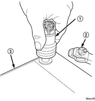
Clean any corrosion from the battery terminal posts with a wire brush or a post and terminal cleaner, and a sodium bicarbonate (baking soda) and warm water cleaning solution.
INSPECTION
The following information details the recommended inspection procedures for the battery and related components. In addition to the maintenance schedules found in this service manual and the owner's manual, it is recommended that these procedures be performed any time the battery or related components must be removed for vehicle service.
- Inspect the battery cable terminal clamps for damage. Replace any battery cable that has a damaged or deformed terminal clamp.
- Inspect the battery tray and battery holddown hardware for damage. Replace any damaged parts.
- Slide the thermal guard off of the battery case (if equipped). Inspect the battery case for cracks or other damage that could result in electrolyte leaks. Also, check the battery terminal posts for looseness. Batteries with damaged cases or loose terminal posts must be replaced.
- Inspect the battery thermal guard for tears, cracks, deformation or other damage (if equipped). Replace any battery thermal guard that has been damaged.
- Inspect the battery built-in test indicator sight glass (if equipped) for an indication of the battery condition. If the battery is discharged, charge as required. Refer to Standard Procedures for detailed instructions.