SWITCH, Horn
DESCRIPTION
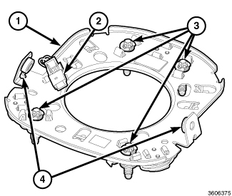 |
A normally open floating-type horn switch and mounting plate (1) is secured to the back of the Driver AirBag (DAB) housing within the hub cavity of the steering wheel. The four sets of switch electrical contacts are each held open by a coiled spring and captured by a mounting screw (3) and E-clips arranged around the perimeter of the mounting plate. A switch wire harness joins the contacts in a parallel circuit to a connector (2) that is connected to the vehicle electrical system through a dedicated take out and connector of the steering wheel wire harness.
The stamped metal switch mounting plate has a mounting tab with
a threaded insert (4) on each side, which is used to secure the DAB
and floating horn switch assembly within the steering wheel hub cavity
with a screw installed through each side of the steering wheel armature.
The floating horn switch contacts, mounting plate and wire harness
are serviced as a unit. If the horn switch is ineffective or damaged,
the entire floating horn switch assembly must be replaced.
OPERATION
When the Driver AirBag (DAB) trim cover in the center of the steering wheel is depressed, the springs between the electrically conductive horn switch contacts are compressed allowing them to contact each other, closing the switch circuit. When the DAB trim cover is released, the springs between the switch contacts expand, opening the switch circuit.
When any one of the four sets of horn switch contacts forms a completed circuit, a horn request signal is provided to the Local Interface Network (LIN) slave node integral to the speed control switch pod in the right horizontal spoke of the steering wheel. The LIN slave node sends an electronic horn switch status message to the LIN master node and Controller Area Network (CAN) data bus gateway integral to the ElectroMechanical Instrument Cluster (EMIC) (also known as the Cab Compartment Node/CCN). The EMIC then relays an electronic horn request message to the Totally Integrated Power Module (TIPM) over the CAN data bus, and the TIPM activates a high side driver to energize the horn feed circuit.
The horn switch as well as the hard wired output circuits for the horn switch may be diagnosed using conventional diagnostic tools and procedures. Refer to the appropriate wiring information.
DIAGNOSIS AND TESTING - HORN SWITCH
To avoid serious or fatal injury
on vehicles equipped with airbags, disable the Supplemental Restraint
System (SRS) before attempting any steering wheel, steering column,
airbag, seat belt tensioner, impact sensor or instrument panel component
diagnosis or service. Disconnect and isolate the battery negative
(ground) cable, then wait two minutes for the system capacitor to
discharge before performing further diagnosis or service. This is
the only sure way to disable the SRS. Failure to take the proper precautions
could result in accidental airbag deployment.
WARNING:
Refer to the appropriate wiring information. The wiring information includes wiring diagrams, proper wire and connector repair procedures, details of wire harness routing and retention, connector pin out information and location views for the various wire harness connectors, splices and grounds.
- Remove the Driver AirBag (DAB) from the steering wheel. (Refer to 10 - Restraints/AIR BAG, Driver - Removal) .
- Disconnect the steering wheel wire harness connector from the horn switch wire harness connector.
- With the horn switch mounting plate released, check for continuity between the two terminals in the horn switch wire harness connector. There should be no continuity. If OK, go to Step 4. If not OK, replace the ineffective horn switch.
- With the horn switch mounting plate depressed, check for continuity between the two terminals in the horn switch wire harness connector. There should now be continuity. If OK, go to Step 5. If not OK, replace the ineffective horn switch.
- Check the steering wheel wire harness for shorts or opens between the horn switch and the speed control switch pod connector. If OK, use a diagnostic scan tool and the appropriate diagnostic procedures for further diagnosis. If not OK, repair or replace the steering wheel wire harness as required.
REMOVAL
To avoid serious or fatal injury
on vehicles equipped with airbags, disable the Supplemental Restraint
System (SRS) before attempting any steering wheel, steering column,
airbag, seat belt tensioner, impact sensor or instrument panel component
diagnosis or service. Disconnect and isolate the battery negative
(ground) cable, then wait two minutes for the system capacitor to
discharge before performing further diagnosis or service. This is
the only sure way to disable the SRS. Failure to take the proper precautions
could result in accidental airbag deployment.
WARNING:
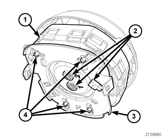 |
- Remove the Driver AirBag (DAB) (1) and floating horn switch (3) from the steering wheel as a unit. (Refer to 10 - Restraints/AIR BAG, Driver - Removal) .
- Pull the DAB and floating horn switch unit away from the steering wheel far enough to access the electrical connections (2) at the back of the unit.
-
Disconnect the steering
wheel wire harness connector from the floating horn switch connector
on the back of the switch.
CAUTION: Do not pull on the clockspring pigtail wires or pry on the connector insulators to disengage them from the Driver AirBag (DAB) inflator initiator connector receptacles. Improper removal of these pigtail wires and their connector insulators can result in damage to the airbag circuits or the connector insulators.
- The clockspring DAB pigtail wire connector insulators are secured by integral latches and a Connector Position Assurance (CPA) lock to the airbag inflator connector receptacles, which are located on the back of the DAB housing. Pull the lock straight out from the connector insulator, then pull the insulators straight out from the airbag inflator to disengage the latches and disconnect them from the connector receptacles.
- Fully loosen each of the four captive screws (4) that secure the floating horn switch unit to the airbag housing.
-
Remove the switch and
mounting plate as a unit from the airbag housing.
INSTALLATION
To avoid serious or fatal injury
on vehicles equipped with airbags, disable the Supplemental Restraint
System (SRS) before attempting any steering wheel, steering column,
airbag, seat belt tensioner, impact sensor or instrument panel component
diagnosis or service. Disconnect and isolate the battery negative
(ground) cable, then wait two minutes for the system capacitor to
discharge before performing further diagnosis or service. This is
the only sure way to disable the SRS. Failure to take the proper precautions
could result in accidental airbag deployment.
WARNING:
|
- Position the floating horn switch and mounting plate unit (3) to the Driver AirBag (DAB) housing (1).
- Install and tighten the four captive screws (4) that secure the switch and mounting plate to the DAB housing. Tighten the screws securely.
- Position the DAB and floating horn switch unit close enough to the steering wheel to reconnect the electrical connections (2) at the back of the airbag housing.
- Reconnect the steering wheel wire harness connector to the floating horn switch connector on the back of the switch.
- Reconnect the wire connectors to the airbag inflator connector receptacles by pressing straight in on the connector insulator. Be certain to engage each keyed and color-coded connector to the matching connector receptacle. You can be certain that each connector is fully engaged in its receptacle by listening carefully for a distinct, audible click as the connector latches snap into place.
- Push each of the Connector Position Assurance (CPA) locks firmly into the DAB connector insulator until it is flush with the upper surface of the insulator.
-
Reinstall the DAB into
the steering wheel. (Refer to
10 - Restraints/AIR BAG, Driver - Installation)
.