SOLENOID, Variable Valve Timing
DESCRIPTION
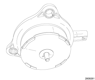 |
The 3.6L engine is equipped with Variable Valve Timing (VVT). This system adjusts the timing of all four camshafts independently using solenoids and oil control valves to direct oil pressure into the camshaft phaser assemblies. The camshaft phaser assembly advances and/or retards camshaft timing to improve engine performance, mid-range torque, idle quality, fuel economy, and reduce emissions. The four VVT solenoids are located on the front of the cylinder head covers. The pintle should move freely within the solenoid body. Do not attempt to disassemble the solenoids, they are not serviceable. The solenoids are identical but should be installed in the same location as removed.
OPERATION
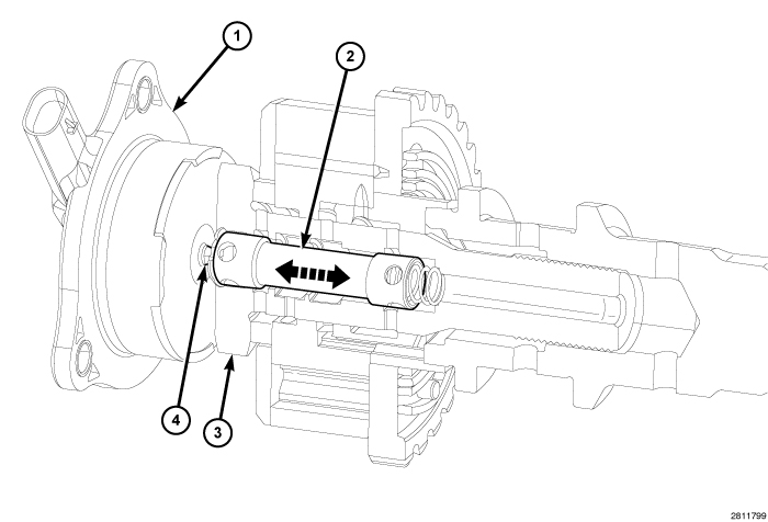 |
Camshaft phaser position is adjusted using regulated oil pressure through an Oil Control Valve (OCV) (3). To begin Phaser movement, the Powertrain Control Module (PCM) applies a pulse-width modulated voltage signal to the VVT solenoid (1) to extend or retract the solenoid pintle (4). The pintle pushes against an internal spool valve (2) within the OCV moving the valve forwards and backwards to direct oil flow. The position of the spool inside the OCV determines which ports and chambers inside the phaser are being fed, either to advance the timing of the phaser sprocket relative to the camshaft, retard it, or hold a desired position (Refer to 09 - Engine/Cylinder Head/ASSEMBLY, Variable Valve Timing - Operation) .
The Camshaft Position (CMP) sensor monitors the position of the camshaft with respect to the crankshaft and provides feedback to the PCM.
The debris crush mode will only occur with the key on and the engine off (KOEO). If the ignition is cycled to the start position without a momentary pause (immediate crank), the debris crush mode will not occur. In this instance the procedure will be performed at the next key off cycle.
LEFT
 |
- Disconnect and isolate the negative battery cable.
-
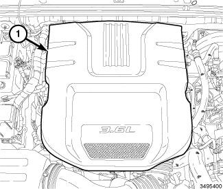
Remove the engine cover (1).
-
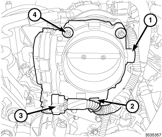
Remove the throttle body (1) (Refer to 14 - Fuel System/Fuel Injection/THROTTLE BODY - Removal)
.
-
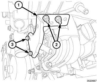
Remove two nuts (2), two bolts (3) and reposition the left front upper intake manifold support bracket (1).
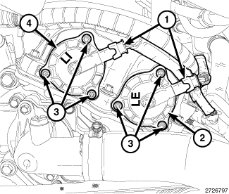
NOTE: Mark the variable valve timing solenoid connectors (1) with a paint pen or equivalent so that they may be reinstalled in their original locations.
- Mark the intake variable valve timing solenoid (4) and the exhaust variable valve timing solenoid (2) with a paint pen or equivalent so that they may be reinstalled in their original locations.
- Disconnect the electrical connector (1) from the variable valve timing solenoid.
-
Remove the variable valve timing solenoid mounting bolts (3).
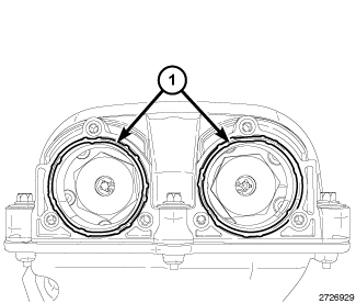
- Pull the variable valve timing solenoid from the cylinder head cover.
-
The seal (1) can be reused if not damaged.
RIGHT
|
- Disconnect and isolate the negative battery cable.
-
Remove the engine cover (1).
-
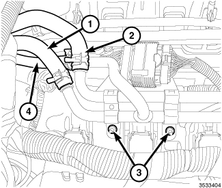
Remove two nuts (3) and reposition the heater core tube assembly.
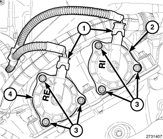
NOTE: Mark the variable valve timing solenoid connectors (1) with a paint pen or equivalent so that they may be reinstalled in their original locations.
- Mark the intake variable valve timing solenoid (2) and the exhaust variable valve timing solenoid (4) with a paint pen or equivalent so that they may be reinstalled in their original locations.
- Disconnect the electrical connector (1) from the variable valve timing solenoid.
-
Remove the variable valve timing solenoid mounting bolts (3).
- Pull the variable valve timing solenoid from the cylinder head cover.
-
The seal (1) can be reused if not damaged.
LEFT
|
-
Install the variable valve timing solenoid seals (1). The seals can be reused if not damaged.
- Refer to the markings made at disassembly and install the intake variable valve timing solenoid (4) and the exhaust variable valve timing solenoid (2) in their original locations.
- Install the variable valve timing solenoid mounting bolts (3) and tighten to 4 N·m (35 in. lbs.).
-
Connect the electrical connector (1) to the variable valve timing solenoid.
-
Install the left front upper intake manifold support bracket (1) with two nuts (2) and two bolts (3). Tighten the nuts (2) to 10 N·m (89 in. lbs.) and tighten the bolts (3) to 10 N·m (89 in. lbs.).
-
Install the throttle body (1) (Refer to 14 - Fuel System/Fuel Injection/THROTTLE BODY - Installation)
.
- Install the engine cover (1).
- Connect the negative battery cable and tighten nut to 5 N·m (45 in. lbs.).
| NOTE: |
The Cam/Crank Variation Relearn procedure must be performed using the scan tool anytime there has been a repair/replacement made to a powertrain system, for example: flywheel, valvetrain, camshaft and/or crankshaft sensors or components. |
RIGHT
|
-
Install the variable valve timing solenoid seals (1). The seals can be reused if not damaged.
- Refer to the markings made at disassembly and install the intake variable valve timing solenoid (2) and the exhaust variable valve timing solenoid (4) in their original locations.
- Install the variable valve timing solenoid mounting bolts (3) and tighten to 4 N·m (35 in. lbs.).
-
Connect the electrical connector (1) to the variable valve timing solenoid.
-
Secure the heater core tube assembly to the right upper intake manifold support bracket with two nuts (3) tightened to 12 N·m (106 in. lbs.).
- Install the engine cover (1).
- Connect the negative battery cable and tighten nut to 5 N·m (45 in. lbs.).
| NOTE: |
The Cam/Crank Variation Relearn procedure must be performed using the scan tool anytime there has been a repair/replacement made to a powertrain system, for example: flywheel, valvetrain, camshaft and/or crankshaft sensors or components. |