CENTER, Electronic Vehicle Information
DESCRIPTION
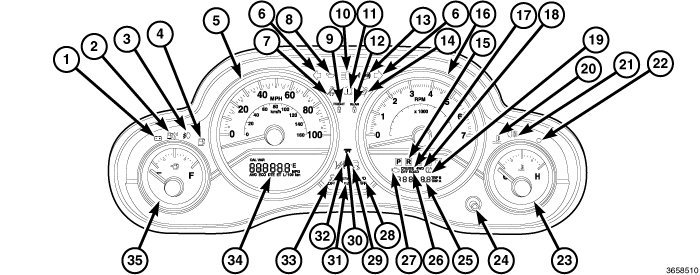 |
The Electronic Vehicle Information Center (EVIC) features a driver-interactive display (34). The display is located in the lower left part of the instrument cluster below the speedometer (5).
The display in the lower right part of the instrument cluster below the tachometer (16) shows the vehicle odometer related functions. These functions include vehicle odometer (ODO), trip odometer A (TRIP A), trip odometer B (TRIP B) readouts and the ECO /ECO-on feature indicator on vehicles so equipped, but not equipped with an EVIC. The instrument cluster odometer and trip odometer select and reset push button (24) can be used to scroll through the different odometer functions and features. (Refer to 08 - Electrical/8J - Instrument Cluster - Description) .
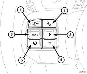 |
The EVIC system conveniently allows the driver to navigate through and select a variety of useful information by pressing the EVIC function buttons located in the EVIC switch pod on the left horizontal spoke of the steering wheel. The EVIC displays information related to the following:
- Audio mode display
- Compass display
- Fuel saver indicator, Economizer (ECO) display (if equipped)
- Navigation system screens (if equipped)
- Outside temperature display
- Personal Settings (customer programmable features)
- System Status
- Tire Pressure Monitor System (TPM) (if equipped)
- Trip computer functions
- UConnect™ hands-free communication system displays (if equipped)
-
Vehicle information warning message displays
The EVIC system includes the following major components:
- Instrument cluster (also known as the Cab Compartment Node/CCN)
- Steering wheel function buttons (also known as the EVIC switch pod)
- Ambient temperature sensor
- Remote Compass Module (RCM)
- Controller Area Network (CAN) data bus
- Local Interface Network (LIN) data bus
The EVIC display is part of the instrument cluster assembly and is not serviced as a separate component. If the display is damaged or ineffective, the complete instrument cluster assembly must be replaced. (Refer to 08 - Electrical/8J - Instrument Cluster - Removal) .
OPERATION
The Electronic Vehicle Information Center (EVIC) uses both non-switched and ignition switched sources of battery current so that some of its features remain operational at any time, while others may only operate with the ignition switch in the “ON” position. When the ignition switch is turned to the “ON” position, the EVIC display will return to the last function being displayed before the ignition was turned to the “OFF” position.
The EVIC system is comprised of several different components that communicate over the Controller Area Network (CAN) and Local Interface Network (LIN) Data Buses. If the system is inoperative a scan tool and the appropriate diagnostic information must be used to diagnose the system.
|
The EVIC function buttons are used to operate the different functions of the EVIC system. Pressing and releasing the MENU button (1) allows the driver to select the Compass/Temperature, Trip Computer, Personal Settings or System Status functions. The STEP button (4) is used to toggle through options or features of the Trip Computer, Personal Settings or System Status functions. Pressing and releasing the RESET button (3) allows the selection of setting or resetting of the function currently displayed at that time. Pressing and releasing the C/T (compass/temperature) button (5) will cause the EVIC to return to the compass/temperature display mode from any other mode.
EVIC DISPLAY MODES
SYSTEM STATUS MODE
System display mode displays warnings and user interaction messages on the EVIC display. The driver can scroll to view multiple messages by using the MENU and STEP buttons. System warnings will always over ride the current display as they become active.
When the appropriate conditions exist, the EVIC displays the following messages:
- Turn Signal On (with a continuous warning chime)
- Left Front Turn Signal Lamp Out (with a single chime)
- Left Rear Turn Signal Lamp Out (with a single chime)
- Right Front Turn Signal Lamp Out (with a single chime)
- Right Rear Turn Signal Lamp Out (with a single chime)
- RKE Battery Low (with a single chime)
- Personal Settings Not Available – Vehicle Not in Park (automatic transmissions) or vehicle in motion (manual transmissions)
- Door (S) Ajar (with a single chime if vehicle is in motion)
- Left Front Low Pressure (with a single chime)
- Left Rear Low Pressure (with a single chime)
- Right Front Low Pressure (with a single chime)
- Right Rear Low Pressure (with a single chime)
- Check TPM System (with a single chime)
- Check Gascap
PERSONAL SETTINGS MODE (CUSTOMER PROGRAMMABLE FEATURES)
Allows the driver to set and recall features when the transmission is in Park by pressing and releasing the MENU button until Personal Settings is displayed in the EVIC. Pressing and releasing the STEP button will scroll through the following personal settings choices:
-
Language When in this display you may select one of five languages for all display nomenclature, including the trip functions and the navigation system (if equipped). Press the RESET button while in this display to select English, Espanol, or Francais. Then, as you continue, the information will display in the selected language.
NOTE: The EVIC will not change the UConnect™ language selection.
- Fuel saver indicator, ECOnomizer (ECO / ECO-on) When the fuel saver indicator ON is selected, the ECO indicator will display below the outside temperature in the EVIC display. This message will display whenever the vehicle is driver in a fuel efficient manner.
- Lock Doors Automatically at 15 mph (24 km/h) When ON is selected, all doors will lock automatically when the vehicle reaches a speed of 15 mph (24 km/h). To make your selection, press and release the RESET button until “ON” or “OFF” appears.
- Unlock Doors Automatically on Exit When ON is selected, all doors will unlock when the vehicle is stopped and the transmission is in the P (Park) or N (Neutral) position and the driver's door is opened. To make your selection, press and release the RESET button until “ON” or “OFF” appears.
- Remote Key Unlock When DRIVER DOOR 1ST PRESS is selected, only the driver's door will unlock on the first press of the remote keyless entry unlock button. When Driver Door 1st Press is selected, you must press the remote keyless entry unlock button twice to unlock the passenger's doors. When ALL DOORS 1ST PRESS is selected, all of the doors will unlock on the first press of the remote keyless entry unlock button. To make your selection, press and release the RESET button until “Driver Door 1st Press” or “All Doors 1st Press” appears.
- Sound Horn with Remote Key Lock When ON is selected, a short horn sound will occur when the remote keyless entry “Lock” button is pressed. This feature may be selected with or without the flash lights on lock/unlock feature. To make your selection, press and release the RESET button until “ON” or “OFF” appears.
- Flash Lights with Remote Key Lock When ON is selected, the front and rear turn signals will flash when the doors are locked or unlocked with the remote keyless entry transmitter. This feature may be selected with or without the sound horn on lock feature selected. To make your selection, press and release the RESET button until “ON” or “OFF” appears.
- Delay Turning Headlights Off When this feature is selected, the driver can choose to have the headlights remain on for 0, 30, 60, or 90 seconds when exiting the vehicle. To make your selection, press and release the RESET button until “0,” “30,” “60,” or “90” appears.
- Turn Headlights On with Remote Key Unlock When this feature is selected, the headlights will activate and remain on for up to 90 seconds when the doors are unlocked with the remote keyless entry transmitter. To make your selection, press and release the RESET button until “OFF,” “30 sec.,” “60 sec.,” or “90 sec.” appears.
- Delay Power Off to Accessories Until Exit When this feature is selected, the power window switches, radio, hands–free system (if equipped), DVD video system (if equipped), power sunroof (if equipped), and power outlets will remain active for up to 60 minutes after the ignition switch is turned off. Opening a vehicle door will cancel this feature. To make your selection, press and release the RESET button until “Off,” “45 sec.,” “5 min.,” or “10 min.” appears.
- Confirmation of Voice Commands — If Equipped When ON is selected, all voice commands from the UConnect™ system are confirmed. To make your selection, press and release the RESET button until “ON” or “OFF” appears.
- Display Units of Measure in The EVIC, odometer, and navigation system (if equipped) can be changed between English and Metric units of measure. To make your selection, press and release the RESET button until “US” or “METRIC” appears.
COMPASS/TEMPERATURE
Compass heading and outside temperature are displayed on the EVIC display screen. One of eight compass headings to indicate the direction the vehicle is facing (N, S, E, W, NE, NW, SE, SW) and one of 15 compass variance settings can be programmed. Outside temperature is displayed in °C (degrees Celsius) or °F (degrees Fahrenheit). The audio mode is always present when the compass/temperature function is displayed.
TRIP COMPUTER
Press and release the MENU button until one of the following Trip Functions displays in the EVIC:
Press the STEP button to cycle through all the Trip Computer functions.
The Trip Functions mode displays the following information:
- Average Fuel Economy Shows the average fuel economy since the last reset. When the fuel economy is reset, the display will read “RESET” or show dashes for two seconds. Then, the history information will be erased, and the averaging will continue from the last fuel average reading before the reset.
- Distance To Empty (DTE) Shows the estimated distance that can be traveled with the fuel remaining in the tank. This estimated distance is determined by a weighted average of the instantaneous and average fuel economy, according to the current fuel tank level. DTE cannot be reset through the RESET button. When the DTE value is less than 30 miles (48 km) estimated driving distance, the DTE display will change to a text display of "LOW FUEL." This display will continue until the vehicle runs out of fuel. Adding a significant amount of fuel to the vehicle will turn off the "LOW FUEL" text and a new DTE value will display.
- Elapsed Time Shows the total elapsed time of travel since the last reset when the ignition switch is in the ACC position. Elapsed time will increment when the ignition switch is in the ON or START position.
- Display Units of Measure in: To make your selection, press and release the RESET button until “US” or “METRIC” appears.
To Reset The Display Reset will only occur while a resettable function is being displayed. Press and release the RESET button once to clear the resettable function being displayed. To reset all resettable functions, press and release the RESET button a second time within 3 seconds of resetting the currently displayed function (>Reset ALL will display during this 3 second window).
HANDS FREE TELEPHONE MODE - IF EQUIPPED
Provides the following information and features for the optional hands-free communications system:
DIAGNOSIS AND TESTING - ELECTRONIC VEHICLE INFORMATION CENTER
Do not place any external magnets,
such as magnetic roof mount antennas, in the vicinity of the Remote
Compass Module (RCM) located above the headliner in the rear of the
vehicle. Do not place any electronic devices (cell phones, laptop
computers, Personal Digital Assistants (PDAs), portable DVD players,
etc.) on or near the rear of the roof as the RCM performance may be
affected. Do not use magnetic tools when servicing the RCM.
CAUTION:
The Electronic Vehicle Information Center (EVIC) data is obtained from several components on the Controller Area Network (CAN) and Local Interface Network (LIN) Data Bus circuits. The EVIC will not function properly if the bus messages from any of these components is not receive. If no EVIC data is displayed or the display indicates dashes "– –", check the CAN and LIN Data Bus circuit communications, the Instrument Cluster functions, the Remote Compass Module (RCM) and the Totally Integrated Power Module (TIPM). Should the RCM become disconnected, the instrument cluster display will go blank.
The use of a scan tool and the proper diagnostic procedure information are recommended for further testing of the Instrument Cluster, the RCM, the CAN Data Bus and the LIN Data Bus circuits. Refer to the appropriate wiring information for complete circuit schematic or connector pin-out information.