MODULE, Compass
- DESCRIPTION
- OPERATION
- DIAGNOSIS AND TESTING - REMOTE COMPASS MODULE
- MANUAL COMPASS CALIBRATION
- COMPASS VARIANCE ADJUSTMENT
- REMOVAL
- INSTALLATION
DESCRIPTION
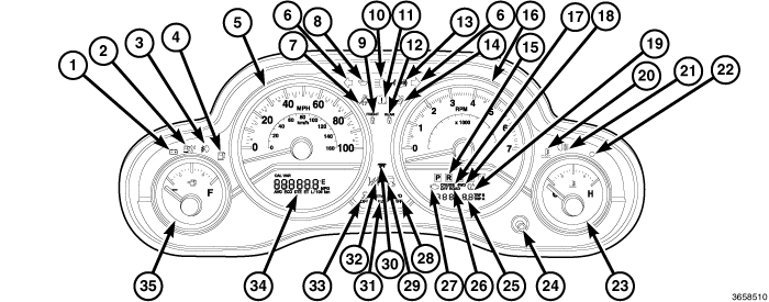 |
The Remote Compass Module (RCM) features two driver-interactive displays. The display located in the lower left part of the instrument cluster (34) at the bottom of the speedometer (5) displays the compass/temperature and trip computer functions. The display located in the lower right part of the instrument cluster (25) at the bottom of the tachometer (16) displays the odometer related functions. This system conveniently allows the driver to select a variety of useful information by depressing the switch buttons of the Electronic Vehicle Information Center (EVIC) switch pod located on the left horizontal spoke of the steering wheel or the odometer and trip odometer select and reset button (24) on the right side of the instrument cluster. Once a resettable feature is displayed, pressing and holding the appropriate reset button will reset the resettable feature. Reset will only occur if a resettable function is currently being displayed. The RCM displays information related to the following:
The RCM system is comprised of several different components. Those components are:
- Instrument Cluster (also known as the Cab Compartment Node/CCN)
- Odometer and trip odometer select and reset button
- EVIC switch module
- Ambient Temperature Sensor
- Remote Compass Module (RCM)
- Controller Area Network (CAN) data bus
- Local Interface Network (LIN) data bus
The RCM display as well as the odometer and trip odometer select and reset button are part of the instrument cluster assembly and cannot be serviced as separate components. If the display or button are damaged or ineffective, the complete instrument cluster assembly must be replaced. (Refer to 08 - Electrical/8J - Instrument Cluster - Removal) .
OPERATION
|
The Remote Compass Module (RCM) uses both non-switched and ignition switched sources of battery current so that some of its features remain operational at any time, while others may only operate with the ignition switch in the ON position. When the ignition switch is turned to the ON position, the RCM display (34) will return to the last function being displayed before the ignition was turned to the OFF position.
The RCM system includes several different components that communicate over the Controller Area Network (CAN) and Local Interface Network (LIN) data buses. If the RCM system is ineffective, a diagnostic scan tool and the appropriate diagnostic information must be used to diagnose the system and the related data buses.
The push buttons of the Electronic Vehicle Information Center (EVIC) switch pod in the left horizontal spoke of the steering wheel are used to navigate through the different functions of the RCM system. Pressing and releasing the STEP button will scroll through the following RCM displays:
Once a resettable function or feature is displayed, pressing and holding the RESET button will reset that resettable function or feature. A reset will only occur if a resettable function or feature is currently being displayed.
The instrument cluster button (24) is the odometer and trip odometer select and reset button, which is used to navigate through the different functions and features of the odometer system. Pressing and releasing this button will scroll through the following displays:
- Odometer (ODO)
- Trip Odometer A (TRIP A)
- Trip Odometer B (TRIP B)
- Fuel saver indicator, Economizer (ECO) display (if equipped)
Once a resettable function or feature is displayed, pressing and holding the odometer and trip odometer reset and select push button will reset that resettable feature or function. Reset will only occur if a resettable function or feature is currently being displayed.
RCM DISPLAY MODES
SYSTEM STATUS MODE
The system status display mode overrides other RCM display modes to display warnings and user interaction messages on the RCM display. The driver can scroll to view multiple messages by using the EVIC STEP button.
When the appropriate conditions exist, the RCM displays the following messages:
- Door(s) Ajar
- Swing Gate Ajar
- Loose Fuel Cap
- No Ignition Off Draw (IOD) Fuse
- Electronic Stability Program (ESP) Off
Each of these messages can be manually acknowledged and turned OFF as they occur by correcting the condition or by pressing either of the EVIC buttons.
COMPASS/TEMPERATURE MODE
Compass heading and outside temperature are displayed on the RCM display screen. One of eight compass headings to indicate the direction the vehicle is facing (N, S, E, W, NE, NW, SE, SW) and one of 15 compass variance (VAR) settings can be displayed. Outside temperature is displayed in °C (degrees Celsius) or °F (degrees Fahrenheit).
AVERAGE FUEL ECONOMY MODE
The average fuel economy (AVG ECO) since the last reset is displayed. When the fuel economy is reset, the display will read RESET or show dashes for two seconds as the history information is being erased. Then the display will show the current (instantaneous) fuel economy and start calculating the new average fuel economy from the point of the most recent reset.
DISTANCE TO EMPTY
| NOTE: |
Significant changes in driving style or vehicle loading will greatly affect the actual drivable distance of the vehicle, regardless of the DTE displayed value. |
Distance to empty (DTE) shows the estimated distance that can be travelled with the fuel remaining in the tank. This estimated distance is determined by a weighted average of the instantaneous and average fuel economy, according to the current fuel tank level. This is not a resettable feature or function.
ELAPSED TIME
Elapsed time (ET) shows the total elapsed time with the ignition switch in the ON position since the most recent reset of this feature.
ODOMETER
Shows the total distance traveled. Press and release the odometer and trip odometer select and reset button on the right side of the instrument cluster to switch from the total odometer to the trip odometer A (TRIP A) or trip odometer B (TRIP B) function. Pressing and holding the select and reset button while either trip odometer is displayed will reset that trip odometer to zero.
TRIP A
Shows the distance traveled for trip odometer A since the last trip odometer A reset. Press and hold the select and reset button while TRIP A is displayed to reset this trip odometer to zero.
TRIP B
Shows the distance traveled for trip odometer B since the last trip odometer B reset. Press and hold the select and reset button while TRIP B is displayed to reset this trip odometer to zero.
FUEL SAVER INDICATOR
If the vehicle is so equipped, the ECO / ECO-on message will display in the odometer display. The message will appear whenever the vehicle is driven in a fuel efficient manner.
DIAGNOSIS AND TESTING - REMOTE COMPASS MODULE
Do not place any external magnets,
such as magnetic roof mount antennas, in the vicinity of the Remote
Compass Module (RCM) located at the top center of the instrument panel.
Do not place any electronic devices (cell phones, laptop computers,
Personal Digital Assistants (PDAs), portable DVD players, etc.) on
or near the instrument panel as the RCM performance may be affected.
Do not use magnetic tools when servicing the RCM.
CAUTION:
The Remote Compass Module (RCM) data is obtained from several components on the Controller Area Network (CAN) and Local Interface Network (LIN) Data Bus circuits. The RCM will not function properly if the bus messages from any of these components is not received. If no RCM data is displayed or the display indicates dashes "– –", check the CAN Data Bus circuit communications, the Instrument Cluster functions, the Remote Compass Module (RCM) and the Totally Integrated Power Module (TIPM). Should the RCM become disconnected, the instrument cluster display will go blank.
The use of a scan tool and the proper diagnostic procedures information are recommended for further testing of the RCM, the CAN Data Bus and Local Interface Network (LIN) Data Bus circuits. Refer to the appropriate wiring information for complete circuit schematic or connector pin-out information.
MANUAL COMPASS CALIBRATION
Do not place any external magnets,
such as magnetic roof mount antennas, in the vicinity of the Remote
Compass Module (RCM) located at the top center of the instrument panel.
Do not place any electronic devices (cell phones, laptop computers,
Personal Digital Assistants (PDAs), portable DVD players, etc.) on
or near the instrument panel as the RCM performance may be affected.
Do not use magnetic tools when servicing the RCM.
CAUTION:
| NOTE: |
Manual calibration is required anytime a new Remote Compass Module (RCM) is installed. Upon installation of the new RCM, the CAL (calibrate) message will appear in the instrument cluster display. The RCM will automatically calibrate if the vehicle is driven very slowly in two or more complete circles, away from large metal objects. The RCM can also be manually calibrated by performing the following procedure. |
| NOTE: |
Confirmation that the proper variance zone is programmed is recommended whenever manual compass calibration is performed. (Refer to 08 - Electrical/8M - Message Systems/Message Center/MODULE, Compass - Standard Procedure) . |
| NOTE: |
If the vehicle is equipped with a Chrysler Uconnect™ GPS (Navigation Radio), the navigation system will provide the compass direction, so the Variance and Calibration menus will be unavailable. The compass performs accurately based upon GPS signals rather than based upon the Earth's magnetic field. |
The electronic compass unit features a self-calibrating design, which simplifies the calibration procedure. This feature automatically updates the compass calibration while the vehicle is being driven. This allows the compass unit to compensate for small changes in the residual magnetism that the vehicle may acquire during normal use. If the compass readings appear to be erratic or the CAL (calibrate) indicator is displayed, perform the appropriate manual calibration procedure. Also, any time a new RCM is installed, it must be manually calibrated using the appropriate procedure.
EXCEPT WITH ELECTRONIC VEHICLE INFORMATION CENTER
|
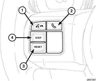 |
In vehicles not equipped with the optional Electronic Vehicle Information Center (EVIC), there are two methods for initiating compass calibration. The compass calibration can be initiated by depressing the odometer/trip odometer push button (24) located on the instrument cluster face just below, and to the right of the odometer; or, by using the RESET push button (3) in the EVIC switch pod (also known as the odometer switch pod) located in the left horizontal spoke of the steering wheel.
Manually calibrate the compass as follows:
| NOTE: |
Do not attempt to calibrate the compass near large metal objects such as other vehicles, large buildings, or bridges; or, near overhead or underground power lines. |
- Start the engine but leave the manual transmission in the Neutral (N) position or the automatic transmission in the Park (P) position.
- Depress and hold the odometer/trip odometer push button or the RESET push button for approximately 10 seconds, until the current variance (VAR) zone number is displayed.
-
Release the odometer/trip odometer push button or the RESET push button, then depress and hold it again for approximately 10 seconds, until the direction is displayed, with the CAL symbol on solid (not blinking) in the display.
NOTE: A blinking CAL symbol within the display indicates the RCM has determined that it is no longer within calibration parameters and the calibration procedure must be performed.
- To complete the compass calibration, drive the vehicle in one or more complete 360 degree circles, under 8 km/h (5 mph) in an area free from overhead or underground power lines and large metal objects such as other vehicles, large buildings or bridges. The CAL symbol will disappear from the display to indicate successful compass calibration.
- Confirm that the correct direction is now indicated by the compass.
| NOTE: |
If the calibration CAL symbol remains in the display or if the compass heading is inaccurate following the calibration procedure and there are no internal compass faults, either there is excessive magnetism near the compass, or the unit is inoperative. Repeat the calibration procedure at least one more time prior to performing any system diagnosis. |
| NOTE: |
If the wrong direction is still indicated in the compass display, the area selected for calibration may be too close to a strong magnetic field. Repeat the calibration procedure in another location. |
WITH ELECTRONIC VEHICLE INFORMATION CENTER
 |
Manually calibrate the compass as follows:
| NOTE: |
Do not attempt to calibrate the compass near large metal objects such as other vehicles, large buildings, or bridges; or, near overhead or underground power lines. |
- Start the engine but leave the manual transmission in the Neutral (N) position or the automatic transmission in the Park (P) position.
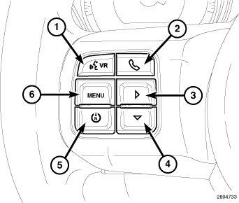
- Depress and release the MENU push button (6), until the Personal Settings (Customer Programmable Features) menu appears in the display.
- Depress and release the Step / Down Scroll push button (4), until Calibrate Compass appears in the display.
-
Depress and release the Select / Reset push button (3) to start the calibration. The CAL symbol should appear solid (not blinking) in the display.
NOTE: A blinking CAL symbol within the display indicates the RCM has determined that it is no longer within calibration parameters and the calibration procedure must be performed.
- To complete the compass calibration, drive the vehicle in one or more complete 360 degree circles, under 8 km/h (5 mph) in an area free from overhead or underground power lines and large metal objects such as other vehicles, large buildings or bridges. The CAL symbol will disappear from the display to indicate successful compass calibration.
- Confirm that the correct direction is now indicated by the compass.
| NOTE: |
If the calibration CAL symbol remains in the display or if the compass heading is inaccurate following the calibration procedure and there are no internal compass faults, either there is excessive magnetism near the compass, or the unit is inoperative. Repeat the calibration procedure at least one more time prior to performing any system diagnosis. |
| NOTE: |
If the wrong direction is still indicated in the compass display, the area selected for calibration may be too close to a strong magnetic field. Repeat the calibration procedure in another location. |
COMPASS VARIANCE ADJUSTMENT
Do not place any external magnets,
such as magnetic roof mount antennas, in the vicinity of the Remote
Compass Module (RCM) located at the top center of the instrument panel.
Do not place any electronic devices (cell phones, laptop computers,
Personal Digital Assistants (PDAs), portable DVD players, etc.) on
or near the instrument panel as the RCM performance may be affected.
Do not use magnetic tools when servicing the RCM.
CAUTION:
| NOTE: |
If the vehicle is equipped with a Chrysler Uconnect™ GPS (Navigation Radio), the navigation system will provide the compass direction, so the Variance and Calibration menus will be unavailable. The compass performs accurately based upon GPS signals rather than based upon the Earth's magnetic field. |
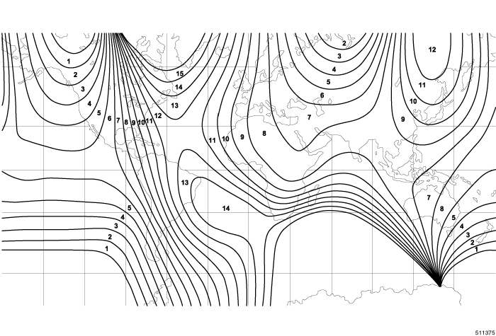 Variance Settings Map |
| NOTE: |
If the vehicle is taken on long trips into a new variance zone, the compass accuracy may be affected. Compass variance may need to be manually adjusted to the proper variance zone setting to restore accurate compass indications. |
| NOTE: |
The factory default for the compass variance zone setting is zone 8. |
Compass variance, also known as magnetic declination, is the difference in angle between magnetic north and geographic north. In some geographic locations, the difference between magnetic and geographic north is great enough to cause the compass to give inaccurate readings. To optimize compass accuracy, the compass variance should be properly set according to the compass variance map zone for the region where the vehicle is being operated.
If the Remote Compass Module (RCM) is being replaced with a new unit, if compass readings appear to be inaccurate or if a manual compass calibration is being performed, check and adjust the variance zone setting using the appropriate procedure.
EXCEPT WITH ELECTRONIC VEHICLE INFORMATION CENTER
|
|
In vehicles not equipped with the optional Electronic Vehicle Information Center (EVIC), there are two methods for checking and adjusting the variance zone setting. The variance zone can be displayed by depressing the odometer/trip odometer push button (24) located on the instrument cluster face just below and to the right of the odometer; or, by using the RESET push button (3) in the EVIC switch pod (also known as the odometer switch pod) located in the left horizontal spoke of the steering wheel. Once the current zone is displayed, it can be adjusted using either the odometer/trip odometer push button on the instrument cluster, or by using the STEP push button (4) in the EVIC switch pod.
To view or adjust the compass variance zone setting:
- Using the Variance Settings Map, find your geographic location and note the zone number.
- Start the engine but leave the manual transmission in the Neutral (N) position or the automatic transmission in the Park (P) position.
-
Depress and hold the odometer/trip odometer push button or the RESET push button for approximately 10 seconds, until the current variance (VAR) zone number is displayed. Then release the push button.
NOTE: The default variance zone number setting is 8. During programming, the variance zone number will wrap around, from zone 15 back to zone 1.
- To change the zone, press and release the odometer/trip odometer push button or the STEP push button to increase the variance zone number upward incrementally. Repeat pressing and releasing the appropriate push button as necessary, until the desired variance zone number is reached.
- After about 10 seconds, the new variance zone number is stored in memory and the compass will resume normal operation.
- Confirm that the correct directions are now indicated by the compass.
WITH ELECTRONIC VEHICLE INFORMATION CENTER
|
To view or adjust the compass variance zone setting:
- Using the Variance Settings Map, find your geographic location and note the zone number.
- Start the engine but leave the manual transmission in the Neutral (N) position or the automatic transmission in the Park (P) position.
- Depress and hold the MENU push button (6), until the Personal Settings (Customer Programmable Features) menu appears in the display.
-
Depress and release the Step / Down Scroll push button (4), until Compass Variance along with the current variance (VAR) zone number appears in the display.
NOTE: The default variance zone number setting is 8. During programming, the variance zone number will wrap around, from zone 15 back to zone 1.
- Depress and release the Select / Reset push button (3) to increase the variance zone number upward incrementally. Repeat pressing and releasing the push button as necessary, until the desired variance zone number is reached.
- After about 10 seconds, the new variance zone number is stored in memory and the compass will resume normal operation.
- Confirm that the correct directions are now indicated by the compass.
REMOVAL
 |
- Disconnect and isolate the battery negative cable.
- Remove the passenger side airbag, (Refer to 10 - Restraints/AIR BAG, Passenger - Removal) .
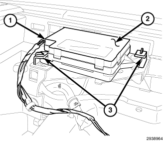
- Release the clips (3) securing the Remote Compass Module (RCM) (2) to the upper instrument panel cover.
-
Disconnect the RCM electrical connector (1) and remove the RCM from the vehicle.
INSTALLATION
Disable the airbag system before
attempting any steering wheel, steering column, or instrument panel
component diagnosis or service. Disconnect and isolate the negative
battery (ground) cable, then wait two minutes for the airbag system
capacitor to discharge before performing further diagnosis or service.
This is the only sure way to disable the airbag system. Failure to
follow these instructions may result in accidental airbag deployment
and possible serious or fatal injury.
WARNING:
|
- Position the Remote Compass Module (RCM) (2) onto the upper instrument panel cover.
- Reconnect the RCM electrical connector (1).
- Reinstall the RCM engaging the clips (3) that secure the module to the upper instrument panel cover.
- Reinstall the passenger airbag into the instrument panel. (Refer to 10 - Restraints/AIR BAG, Passenger - Installation) .
- Reconnect the battery negative cable.
| NOTE: |
The Remote Compass Module (RCM) must be calibrated following installation. (Refer to 08 - Electrical/8M - Message Systems/Message Center/MODULE, Compass - Standard Procedure)
. |