MICROPHONE
DESCRIPTION
Vehicles equipped with the hands free phone system have a microphone mounted above a grille in the driver side upper A-pillar trim located outboard of the driver side sun visor near the upper windshield frame. The microphone is powered by and provides a hard wired input to the Radio Receiver Module (RRM) (also known as the radio or the head unit) in the instrument panel whenever the Voice Recognition (VR) feature of the hands free phone system is active. This microphone is connected to the vehicle electrical system through a dedicated pigtail wire harness and connector to a dedicated take out and connector of the instrument panel wire harness.
The microphone cannot be adjusted or repaired and, if damaged or
ineffective, it must be replaced.
OPERATION
When the hands free phone system Voice Recognition (VR) control circuitry integral and internal to the Radio Receiver Module (RRM) (also known as the radio or the head unit) detects the appropriate inputs or requests, it energizes the circuitry of the microphone behind the driver side upper A-pillar trim. The microphone remains active until it is deactivated by the hands free phone VR control circuitry, or until the status of the ignition switch transitions to Off, whichever occurs first.
The input from the microphone is processed, filtered and redirected by the VR control circuitry and logic as appropriate. Those inputs can be redirected to the Advanced Speech Recognition (ASR) engine or to the audio send circuitry of the Bluetooth™ transceiver within the Hands Free Module (HFM) (also known as the Bluetooth™ module).
The hard wired inputs and outputs of the microphone may be diagnosed using conventional diagnostic tools and procedures. Refer to the appropriate wiring information. However, conventional diagnostic methods will not prove conclusive in the diagnosis of the microphone or the electronic controls and communication between modules and other devices that provide some features of the RRM controlled microphone. The most reliable, efficient and accurate means to diagnose the RRM or the electronic controls and communication related to RRM-controlled microphone operation requires the use of a diagnostic scan tool. Refer to the appropriate diagnostic information.
DIAGNOSIS AND TESTING - MICROPHONE
To avoid serious or fatal injury
on vehicles equipped with airbags, disable the Supplemental Restraint
System (SRS) before attempting any steering wheel, steering column,
airbag, seat belt tensioner, impact sensor or instrument panel component
diagnosis or service. Disconnect and isolate the battery negative
(ground) cable, then wait two minutes for the system capacitor to
discharge before performing further diagnosis or service. This is
the only sure way to disable the SRS. Failure to take the proper precautions
could result in accidental airbag deployment.
WARNING:
The hard wired inputs and outputs of the microphone behind the driver side upper A-pillar trim may be diagnosed using conventional diagnostic tools and procedures. Refer to the appropriate wiring information. However, conventional diagnostic methods will not prove conclusive in the diagnosis of the microphone or the electronic controls and communication between modules and other devices that provide some features of the Radio Receiver Module (RRM) (also known as the radio or the head unit) controlled microphone. The most reliable, efficient and accurate means to diagnose the RRM or the electronic controls and communication related to RRM-controlled microphone operation requires the use of a diagnostic scan tool. Refer to the appropriate diagnostic information.
REMOVAL
-
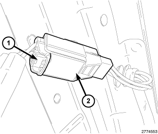
- Disconnect and isolate the negative cable from the battery.
- Remove the upper trim from the driver side A-pillar. (Refer to 23 - Body/Interior/PANEL, A-Pillar Trim - Removal) .
-
Disconnect the microphone
pigtail wire harness connector (1) from the instrument panel wire
harness connector (2).
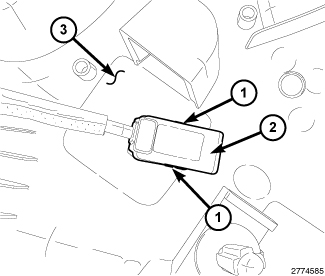
-
Remove the microphone
(2) from the receptacle on the back side of the upper A-pillar trim
(3) by carefully pushing in the latch tabs (1) on each side of the
microphone and pulling the microphone out of the receptacle.
INSTALLATION
|
-
Align and insert the
microphone (2) with the receptacle on the back of the driver side
upper A-pillar trim (3) until the latch tabs (1) on each side of the
microphone snap into place.
- Reconnect the microphone pigtail wire harness connector (1) to the instrument panel wire harness connector (2).
-
Reinstall the upper
trim onto the driver side A-pillar. (Refer to 23 - Body/Interior/PANEL, A-Pillar Trim - Installation)
.