MODULE, Power, Blower Motor
DESCRIPTION
| NOTE: |
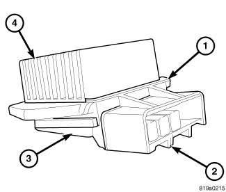
ATC blower motor power module shown. MTC power module similar. |
 |
A blower motor power module is used on this model when equipped with either the Automatic Temperature Control (ATC) heating-A/C system, or the Manual Temperature Control (MTC) heating-A/C system.
The blower motor power module is mounted to the bottom of the HVAC housing, on the passenger side of the vehicle. The blower motor power module consists of a molded plastic mounting plate (1) with an integral connector receptacle (2). Concealed behind the mounting plate is the power module electronic circuitry (3) and a finned aluminum heat sink (4). The blower motor power module is accessed for service from under the instrument panel.
OPERATION
The blower motor power module is connected to the vehicle electrical system through a dedicated lead and connector of the instrument panel wire harness. A second lead and connector of the instrument panel wire harness is connected to the blower motor.
On the Automatic Temperature Control (ATC) system, the blower motor power module allows the microprocessor-based A/C-heater control to calculate and provide infinitely variable blower motor speeds based upon either manual blower switch input or the ATC programming.
On the Manual Temperature Control (MTC) system, the blower motor power module allows the microprocessor-based A/C-heater control to provide an infinite amount of blower motor speeds throughout its operating range, based upon blower switch input.
Both the ATC and MTC systems use a Pulse Width Modulated (PWM) circuit strategy. PWM voltage is applied to a comparator circuit which compares the PWM signal voltage to the blower motor feedback voltage. The resulting output drives the power module circuitry, which provides a linear output voltage to change or maintain the desired blower speed.
The blower motor power module is diagnosed using a scan tool (Refer to 28 - DTC-Based Diagnostics/HVAC - Diagnosis and Testing) .
The blower motor power module cannot be adjusted or repaired must be replaced if inoperative or damaged.
REMOVAL
Disable the airbag system before
attempting any steering wheel, steering column or instrument panel
component diagnosis or service. Disconnect and isolate the negative
battery (ground) cable, then wait two minutes for the airbag system
capacitor to discharge before performing further diagnosis or service.
This is the only sure way to disable the airbag system. Failure to
follow these instructions may result in accidental airbag deployment
and possible serious or fatal injury.
WARNING:
The heat sink for the blower motor
power module may get very hot during normal operation. If the blower
motor was turned on prior to servicing the blower motor power module,
wait five minutes to allow the heat sink to cool before performing
diagnosis or service. Failure to follow these instructions may result
in possible serious injury.
WARNING:
| NOTE: |
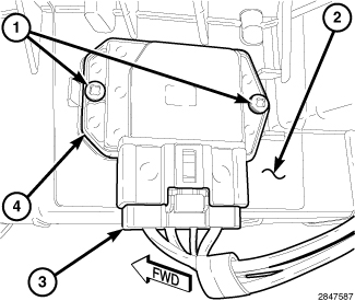
ATC blower motor power module shown. MTC power module similar. |
 |
- Disconnect and isolate the negative battery cable.
- If equipped, remove the two push-pins and silencer panel from the passenger side of the instrument panel.
- Disconnect the wire harness connector (3) from the blower motor power module (4).
-
Remove the two screws (1) that secure the blower motor power module to the HVAC housing (2) and remove the power module.
INSTALLATION
| NOTE: |
ATC blower motor power module shown. MTC power module similar. |
|
- Position the blower motor power module (4) into the HVAC housing (2).
- Install the two screws (1) that secure the blower motor power module to the HVAC housing. Tighten the screws to 1.2 N·m (10 in. lbs.).
- Connect the wire harness connector (3) to the blower motor power module.
- If equipped, install the passenger side silencer panel and two push-pins.
-
Reconnect the negative battery cable.