ASSEMBLY, Variable Valve Timing, Phaser / Oil Control Valve
DESCRIPTION
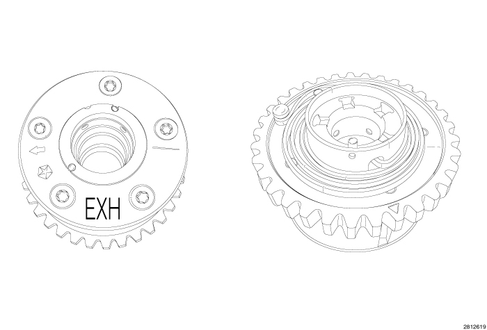 |
The engine is equipped with Variable Valve Timing (VVT). This system adjusts the timing of all four camshafts independently using solenoids and oil control valves to direct oil pressure into the camshaft phaser assemblies. The camshaft phaser assembly advances and/or retards camshaft timing to improve engine performance, mid-range torque, idle quality, fuel economy, and reduce emissions. The four phasers are located on the front of the camshafts, behind the VVT solenoids, inside of the engine timing cover. The exhaust phasers are identified with EXH and the intake phasers are identified with INT. The exhaust phaser has a clockspring, the intake phaser does not. The camshaft sprockets are integrated with the camshaft phaser and are serviced as an assembly. Do not attempt to disassemble the phasers, they are not serviceable. Phasers are interchangeable between the right and left cylinder heads but should be installed in the same location as removed.
The engine has an Oil Control Valve (OCV) for each phaser. The OCV also acts as a bolt for mounting the Phaser to the camshaft. The OCVs spool valve is spring loaded and should move freely within the OCV body. The four OCVs are identical but should be installed in the same location as removed.
OPERATION
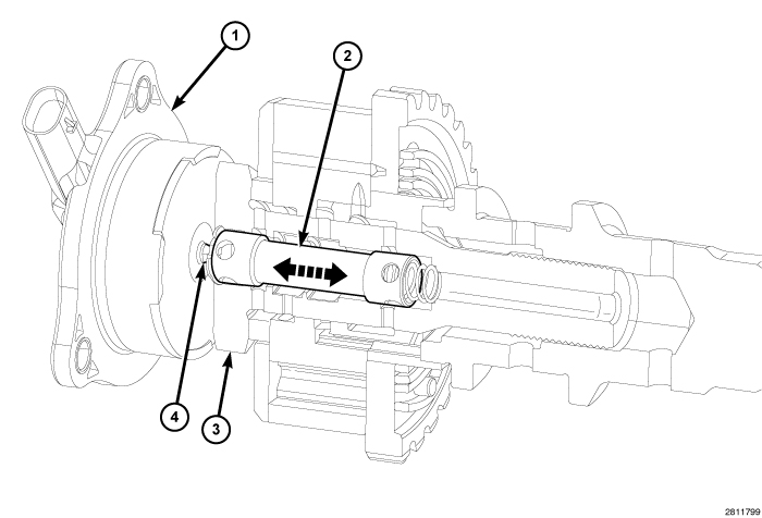 |
Each phaser position is adjusted using regulated oil pressure through the Oil Control Valve (OCV) (3). To begin phaser movement, a voltage signal is applied to the VVT solenoid (1) to extend or retract the solenoid pintle (4). The pintle pushes against an internal spool valve (2) within the OCV moving the valve forwards and backwards to direct oil flow.
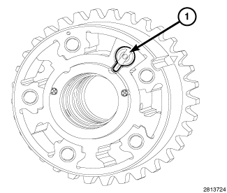 |
At engine startup, system oil pressure overcomes spring pressure and unlocks the phaser lock-pin (1) in preparation for phasing. The phasers remain in this position until a PCM signal is given to pulse-width modulate the VVT solenoid. At engine shutdown, as oil pressure is reduced, both Phasers return to their lock-pin position (1). However, because the exhaust Phaser needs to travel to a position above and beyond the standard camshaft clockwise rotation, the assistance of a clock spring is required. The intake Phaser on the other hand, simply relies on the torsional resistance from the valvetrain to push it back towards lock-pin position.
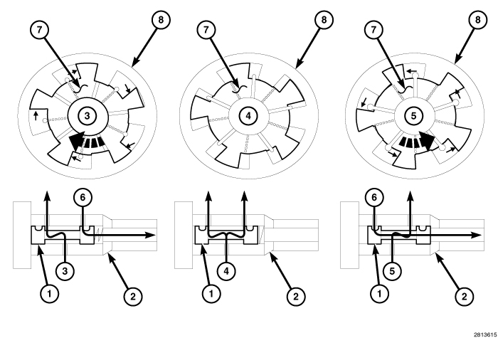 |
The position of the spool valve (1) inside the OCV (2) determines which ports and chambers inside the phaser are being fed, either to advance (3), hold (4) or retard (5) the timing of the phaser sprocket relative to the camshaft. The spool valve also returns oil from the chambers to the sump (6). The Camshaft Position (CMP) sensor monitors the position of the camshaft with respect to the crankshaft and provides feedback to the PCM. As oil pressure pushes against the vanes (6) of the phaser rotor, the rotor begins to move. Since this rotor is physically attached to the camshaft, rotor rotation causes the camshaft position to rotate relative to the standard sprocket (7) position.
LEFT
 |
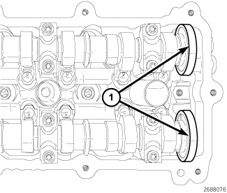 |
The magnetic timing wheels (1)
must not come in contact with magnets (pickup tools, trays, etc.)
or any other strong magnetic field. This will destroy the timing wheels
ability to correctly relay camshaft position to the camshaft position
sensor.
CAUTION:
 |
- Remove the upper intake manifold, left ignition coils and left cylinder head cover (Refer to 09 - Engine/Cylinder Head/COVER(S) , Cylinder Head - Removal)
-
Remove the right ignition
coils and all spark plugs (Refer
to 08 - Electrical/8I - Ignition Control/SPARK PLUG - Removal)
.
CAUTION: When aligning timing marks, always rotate engine by turning the crankshaft. Failure to do so will result in valve and/or piston damage.
-
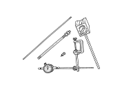
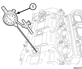
Mount Dial Indicator
Set C-3339A (1) to a stationary point on the engine, such as the number
three cylinder ignition coil mount. Position the indicator probe into
the number one cylinder, rotate the crankshaft clockwise (as viewed
from the front) to place the number one cylinder piston at top-dead-center
on the exhaust stroke and set the indicator dial to zero.
-
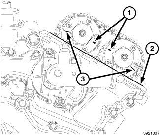
The left side cam phaser SCRIBE LINES (3)
should face away from each other and the ARROWS (1) should
point toward each other and be parallel to the cylinder head cover
mounting surface (2) when the number one cylinder piston is positioned
at top-dead-center on the exhaust stroke.
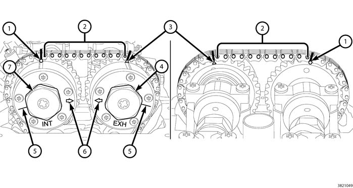
NOTE: The cam phaser timing markings (1 and 3) could align with either an external or internal chain link. Either alignment is acceptable as long as there are twelve chain pins (2) between the markings.
NOTE: Using a paint pen or equivalent. Mark the timing chain links to the corresponding timing marks located on the cam phasers.
- There should be twelve chain pins (2) BETWEEN the exhaust cam phaser triangle marking (3) and the intake cam phaser circle marking (1) as viewed from either the front or rear of the cam phasers.
-
Mark both sides of
the cam chain at the phaser timing marks (1 and 3) using a paint pen
or equivalent to aid in reassembly.
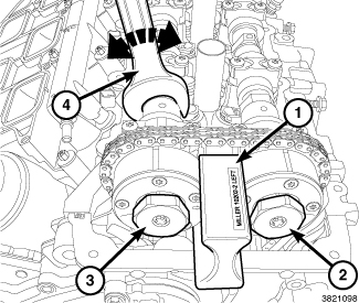
NOTE: It may be necessary to rock the camshaft slightly (a few degrees) with a wrench (4) when installing the camshaft phaser lock.
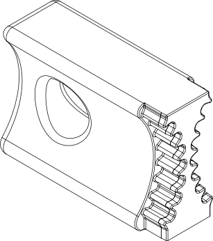
- Install the Lock, Camshaft/Phaser, Left Side 10202-2 (1) against the cylinder head cover mounting surface with the tool number facing up.
- Loosen, but do not remove, the exhaust oil control valve (2) and the intake oil control valve (3).
-
Remove the
Lock, Camshaft/Phaser, Left Side 10202-2 (1).
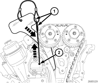
NOTE: Graphic shows engine timing cover removed for clarity.
-
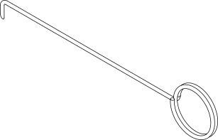
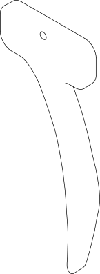
Using
Pin 10200-3 (2), lift the pawl off of the rack (3). While holding the
pawl off of the rack, push
Holder, Timing Chain, Left Side 10200-1 (1) into place between the cylinder head and the cam chain
guide to force the rack and piston back into the tensioner body. The
holder remains in place while the phasers are removed (Refer to 09 - Engine/Valve Timing
- Standard Procedure)
.
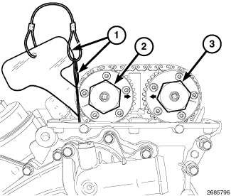
- Remove the oil control valve (4) and pull the left side exhaust cam phaser off of the camshaft.
-
Remove the oil control
valve (3) and pull the left side intake cam phaser off of the camshaft.
RIGHT

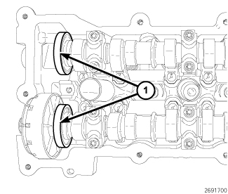 |
The magnetic timing wheels (1)
must not come in contact with magnets (pickup tools, trays, etc.)
or any other strong magnetic field. This will destroy the timing wheels
ability to correctly relay camshaft position to the camshaft position
sensor.
CAUTION:
 |
- Remove the upper intake manifold, right ignition coils and right cylinder head cover (Refer to 09 - Engine/Cylinder Head/COVER(S) , Cylinder Head - Removal)
-
Remove the left ignition
coils and all spark plugs (Refer
to 08 - Electrical/8I - Ignition Control/SPARK PLUG - Removal)
.
CAUTION: When aligning timing marks, always rotate engine by turning the crankshaft. Failure to do so will result in valve and/or piston damage.
-
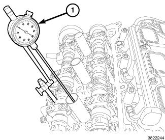
Mount Dial Indicator
Set C-3339A (1) to a stationary point on the engine, such as the cylinder
head cover mounting surface. Position the indicator probe into the
number one cylinder, rotate the crankshaft clockwise (as viewed from
the front) to place the number one piston at top-dead-center on the
exhaust stroke and set the indicator dial to zero.
-
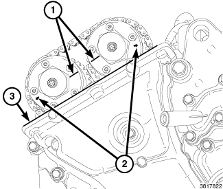
The right side cam
phaser ARROWS (2) should point away from each other and the SCRIBE LINES (1)
should be parallel to the cylinder head cover mounting surface (3)
when the right side number one cylinder piston is positioned at top-dead-center
on the exhaust stroke.
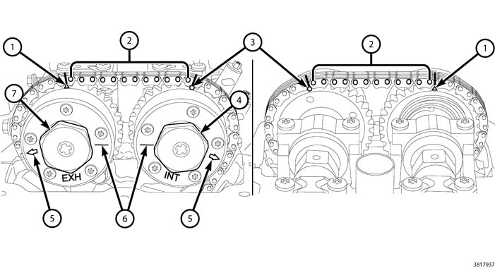
NOTE: The phaser markings (1 and 3) could align with either an external or internal chain link. Either alignment is acceptable as long as there are twelve chain pins (2) between the markings.
NOTE: Using a paint pen or equivalent. Mark the timing chain links to the corresponding timing marks located on the cam phasers.
- There should be twelve chain pins (2) BETWEEN the exhaust cam phaser triangle marking (1) and the intake cam phaser circle marking (3) as viewed from either the front or rear of the cam phasers.
-
Mark both sides of
the cam chain at the phaser timing marks (1 and 3) using a paint pen
or equivalent to aid in reassembly.
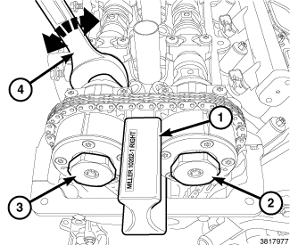
NOTE: It may be necessary to rock the camshaft slightly (a few degrees) with a wrench (4) when installing the camshaft phaser lock.
- Install the Lock, Camshaft/Phaser, Right Side 10202-1 (1) against the cylinder head cover mounting surface with the tool number facing up.
- Loosen, but do not remove, the exhaust oil control valve (3) and the intake oil control valve (2).
-
Remove the
Lock, Camshaft/Phaser, Right Side 10202-1 (1).
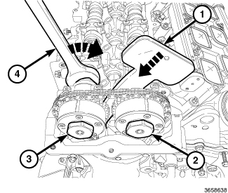
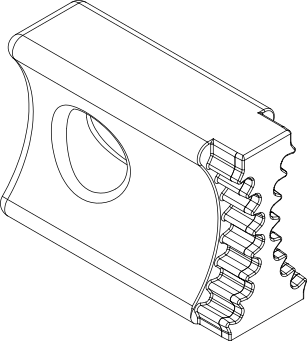
CAUTION: Do not insert the Timing Chain Holder into position without first compressing the tensioner. The Timing Chain Holder is not designed to compress the tensioner and excessive force can damage the timing chain tensioner arm.
-
Use the timing chain
to compress the tensioner by slightly rotating the exhaust camshaft
clockwise (4). Insert
Holder, Timing Chain 10369 (1) into place between the cylinder head boss and the tensioner
arm to hold the tensioner in the compressed position. The Timing Chain
Holder remains in place while the phasers are removed.
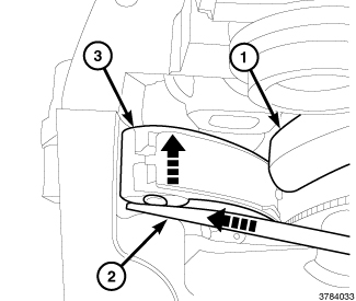
NOTE: If the Timing Chain Holder (1) does not engage or slips from position, wedge a trim stick (2) or equivalent between the front cover and the tensioner arm (3) to push the tensioner arm towards the rear of the engine and then repeat the previous step.
- Remove the oil control valve (3) and pull the right side exhaust cam phaser off of the camshaft.
-
Remove the oil control
valve (2) and pull the right side intake cam phaser off of the camshaft.
LEFT
 |
|
The magnetic timing wheels (1)
must not come in contact with magnets (pickup tools, trays, etc.)
or any other strong magnetic field. This will destroy the timing wheels
ability to correctly relay camshaft position to the camshaft position
sensor.
CAUTION:
|
Do not rotate the crankshaft more
than a few degrees independently of the camshafts. Piston to valve
contact could occur resulting in possible valve damage. If the crankshaft
needs to be rotated more than a few degrees, first remove the camshafts
.
CAUTION:
-
Verify that the indicator
dial (1) is set to zero when the right side number one cylinder piston
is positioned at top-dead-center on the exhaust stroke.
-
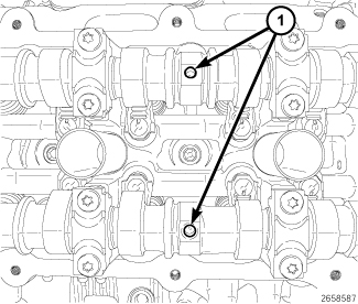
Verify that the camshafts are set at top-dead-center by positioning the alignment holes (1) vertically.CAUTION: Do not rotate the camshafts more than a few degrees independently of the crankshaft. Valve to piston contact could occur resulting in possible valve damage.
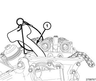
NOTE: The Timing Chain Holder (1) should still be in place as inserted during the Removal procedure. If required, the Timing Chain Holder can be reinserted by repeating Step 10 of the Removal procedure (Refer to 09 - Engine/Cylinder Head/ASSEMBLY, Variable Valve Timing - Removal) .
NOTE: Minor rotation of a camshaft (a few degrees) may be required to install the camshaft phaser.
- Route the cam chain around the left intake cam phaser while aligning the paint mark with the phaser timing mark (1). Press the left intake cam phaser onto the intake camshaft. Install and hand tighten the oil control valve (7).
- While maintaining this alignment, route the cam chain around the exhaust cam phaser so that the paint mark is aligned with the phaser timing mark (3). Press the exhaust cam phaser onto the exhaust cam, install and hand tighten the oil control valve (4).
-
The SCRIBE LINES (5)
on the cam phasers should face away from each other and the ARROWS (6) should
point toward each other and be parallel to the cylinder head cover
mounting surface. There should be twelve chain pins (2) BETWEEN the exhaust
cam phaser triangle marking (3) and the intake cam phaser circle marking
(1).
NOTE: It may be necessary to rock the camshaft slightly (a few degrees) with a wrench (4) when installing the camshaft phaser lock.
- Install the Lock, Camshaft/Phaser, Left Side 10202-2 (1) against the cylinder head cover mounting surface with the tool number facing up.
- Tighten the oil control valves (2) and (3) to 150 N·m (110 ft. lbs.).
-
Remove the Camshaft
Phaser Lock (1) and the Timing Chain Holder.
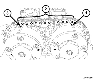
-
Rotate the crankshaft
clockwise two complete revolutions stopping when the right side number
one cylinder piston is again positioned at top-dead-center on the
exhaust stroke. To assure correct engine timing, verify the following;
- The indicator dial is set to ZERO when the right side number one cylinder piston is positioned at top-dead-center on the exhaust stroke.
- The SCRIBE LINES (3) on the left side cam phasers face away from each other.
- The ARROWS (4) on the left side cam phasers point toward each other and are parallel to the cylinder head cover mounting surface.
- There are twelve chain pins (2) BETWEEN the exhaust cam phaser triangle marking (1) and the intake cam phaser circle marking (3).
-
If the engine timing
is not correct, repeat this procedure.
- Install the spark plugs (Refer to 08 - Electrical/8I - Ignition Control/SPARK PLUG - Installation) .
- Install the right ignition coils (Refer to 08 - Electrical/8I - Ignition Control/COIL, Ignition - Installation)
- Install the left cylinder head cover and left ignition coils (Refer to 09 - Engine/Cylinder Head/COVER(S) , Cylinder Head - Installation)
- Install the upper intake manifold and air cleaner housing assembly (Refer to 09 - Engine/Manifolds/MANIFOLD, Intake - Installation)
- Connect the negative battery cable and tighten nut to 5 N·m (45 in. lbs.).
- Start the engine and perform the following Powertrain Verification Tests (Refer to 28 - DTC-Based Diagnostics/MODULE, Powertrain Control (PCM) - Standard Procedure):
| NOTE: |
Following the first restart after a DTC driven phaser replacement, clear all DTCs and verify that subsequent restarts do not set any additional codes. (Refer to 28 - DTC-Based Diagnostics/MODULE, Powertrain Control (PCM) - Diagnosis and Testing) for any DTCs that reset. |
RIGHT
|
|
The magnetic timing wheels (1)
must not come in contact with magnets (pickup tools, trays, etc.)
or any other strong magnetic field. This will destroy the timing wheels
ability to correctly relay camshaft position to the camshaft position
sensor.
CAUTION:
|
Do not rotate the crankshaft more
than a few degrees independently of the camshafts. Piston to valve
contact could occur resulting in possible valve damage. If the crankshaft
needs to be rotated more than a few degrees, first remove the camshafts
.
CAUTION:
-
Verify that the indicator
dial (1) is set to zero when the right side number one cylinder piston
is positioned at top-dead-center on the exhaust stroke.
-
Verify that the camshafts are set at top-dead-center by positioning the alignment holes (1) vertically.CAUTION: Do not rotate the camshafts more than a few degrees independently of the crankshaft. Valve to piston contact could occur resulting in possible valve damage.
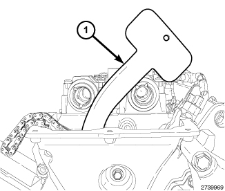
NOTE: The Timing Chain Holder (1) should still be in place as inserted during the Removal procedure. If required, the Timing Chain Holder can be reinserted by installing the exhaust cam phaser and repeating Step 10 of the Removal procedure (Refer to 09 - Engine/Cylinder Head/ASSEMBLY, Variable Valve Timing - Removal) .
NOTE: Minor rotation of a camshaft (a few degrees) may be required to install the camshaft phaser.
- Route the cam chain around the right exhaust cam phaser while aligning the paint mark with the phaser timing mark (1). Press the right exhaust cam phaser onto the exhaust camshaft. Install and hand tighten the oil control valve (7).
- While maintaining this alignment, route the cam chain around the intake cam phaser so that the paint mark is aligned with the phaser timing mark (3). Press the intake cam phaser onto the intake cam, install and hand tighten the oil control valve (4).
-
The ARROWS (5) on the
cam phasers should point away from each other and the SCRIBE LINES (6)
should be parallel to the cylinder head cover mounting surface. There
should be twelve chain pins (2) BETWEEN the exhaust
cam phaser triangle marking (1) and the intake cam phaser circle marking
(3).
NOTE: It may be necessary to rock the camshaft slightly (a few degrees) with a wrench (4) when installing the camshaft phaser lock.
- Install the Lock, Camshaft/Phaser, Right Side 10202-1 (1) against the cylinder head cover mounting surface with the tool number facing up.
- Tighten the oil control valves (2) and (3) to 150 N·m (110 ft. lbs.).
-
Remove the Camshaft
Phaser Lock (1) and the Timing Chain Holder.
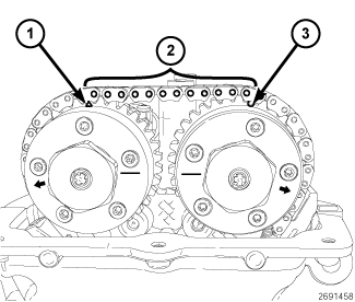
-
Rotate the crankshaft
clockwise two complete revolutions stopping when the right side number
one cylinder piston is again positioned at top-dead-center on the
exhaust stroke. To assure correct engine timing, verify the following;
- The indicator dial is set to ZERO when the right side number one cylinder piston is positioned at top-dead-center on the exhaust stroke.
- The ARROWS (4) on the right side cam phasers point away from each other.
- The SCRIBE LINES (5) on the right side cam phasers are parallel to the cylinder head cover mounting surface.
- There are twelve chain pins (2) BETWEEN the exhaust cam phaser triangle marking (1) and the intake cam phaser circle marking (3).
-
If the engine timing
is not correct, repeat this procedure.
- Install the spark plugs (Refer to 08 - Electrical/8I - Ignition Control/SPARK PLUG - Installation) .
- Install the left ignition coils (Refer to 08 - Electrical/8I - Ignition Control/COIL, Ignition - Installation)
- Install the right cylinder head cover and right ignition coils (Refer to 09 - Engine/Cylinder Head/COVER(S) , Cylinder Head - Installation)
- Install the upper intake manifold and air cleaner housing assembly (Refer to 09 - Engine/Manifolds/MANIFOLD, Intake - Installation)
- Connect the negative battery cable and tighten nut to 5 N·m (45 in. lbs.).
- Start the engine and perform the following Powertrain Verification Tests (Refer to 28 - DTC-Based Diagnostics/MODULE, Powertrain Control (PCM) - Standard Procedure):
| NOTE: |
Following the first restart after a DTC driven phaser replacement, clear all DTCs and verify that subsequent restarts do not set any additional codes. (Refer to 28 - DTC-Based Diagnostics/MODULE, Powertrain Control (PCM) - Diagnosis and Testing) for any DTCs that reset. |