CAMSHAFT, Engine
DESCRIPTION
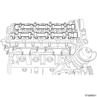 |
The camshafts are made of cast iron with eight machined lobes and
four bearing journals.
 |
-
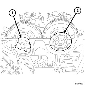
The exhaust camshaft
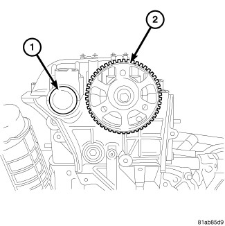
(1) incorporates the CMP sensor reluctor wheel. The intake camshaft
uses a camshaft seal (2).
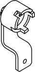
NOTE: Starting in model year 2013, the exhaust camshaft reluctor is now bolted on requiring a change in the Camshaft Sprocket Alignment Tool VM.9991. The new Camshaft Sprocket Alignment Tool number is VM.9991–1. This tool can be used on older models.
-
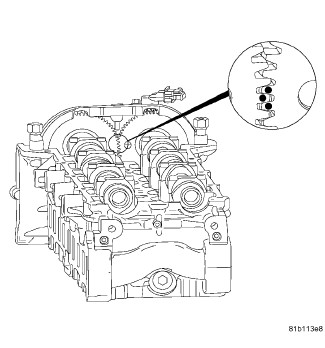
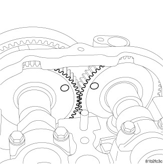
The dots on the back
of the camshaft gears are for initial timing only. These dots are
for timing the camshafts to each other. To correctly set engine timing,
the camshafts must be set to 90° ATDC. The Camshaft Locking Tool VM.9991 is used to correctly set the camshafts to their proper location.
REMOVAL
 |
- Disconnect the negative battery cable.
-
Remove the intake camshaft sprocket (2) (Refer to 09 - Engine/Valve Timing/SPROCKET(S)
, Timing Belt and Chain - Removal).
-
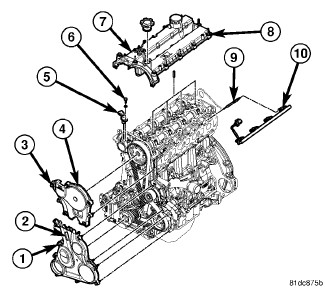
Remove the cylinder head cover (7) (Refer to 09 - Engine/Cylinder Head/COVER(S)
, Cylinder Head - Removal).
-
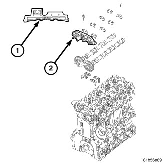
Remove the front cam bearing journal (2).
-
Remove the intake camshaft oil seal (2).
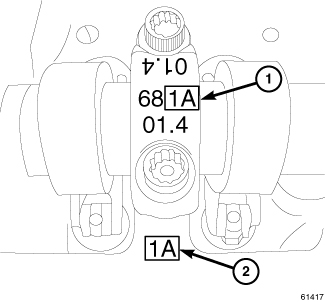
NOTE: Observe the position marks on the cylinder head and camshaft cap as a reference to its original location. The illustration is an example of the camshaft markings.
NOTE: Intake and exhaust manifolds removed for clarity.
- Using a circular pattern, remove bolts and the camshaft bearing caps.
-
Remove the camshafts.
INSTALLATION
|
-
Lubricate the camshaft
journals with Mopar® Engine Oil Supplement, or equivalent.
NOTE: The dots on the back of the camshaft gears are for initial timing only. These dots are for timing the camshafts to each other. To correctly set engine timing, the camshafts must be set to 90° ATDC. The camshaft locking tool is used to correctly set the camshafts to their proper location.
- Make sure that the three small orientation dots marks on the back side of the camshaft gears are horizontal and facing each other.
-
Carefully install camshafts
onto the camshaft journals.
-
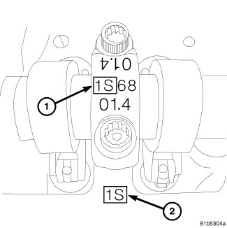
The cylinder head and
camshaft caps have markings to identify each cap to its correct location.
In the illustration, 1S (1) is marked on the exhaust side camshaft
cap and 1S (2) is the mark on the exhaust side of the cylinder head.
It is critical that all of the camshaft caps are returned to their
correct locations.
-
The cylinder head and
camshaft caps have markings to identify each cap to its correct location.
In the illustration, 1A (1) is marked on the intake side camshaft
cap and 1A (2) is the mark on the intake side of the cylinder head.
It is critical that all of the camshaft caps are returned to their
correct locations.
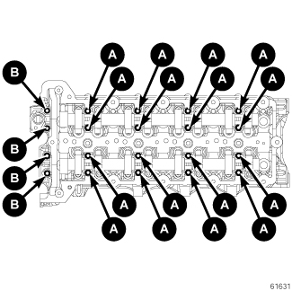
NOTE: Whenever the camshaft caps are removed, always replace the bolts.
-
The camshaft bolts
have 2 different bolt sizes.
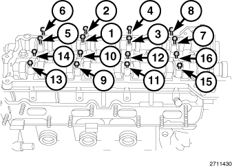
-
Using new bolts and
the tightening sequence shown, install the camshaft bolts and tighten
bolts in one turn increments until finger tight.
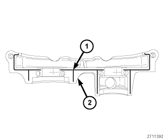
NOTE: Be careful not to get ant Loctite® 510 onto the camshaft journal.
- Apply a thin bead of Loctite® 510 to the front camshaft bearing journal (2) in the location illustrated (1).
-
Install the front camshaft
bearing journal and tighten the new bolts finger tight.
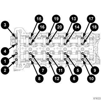
-
Using the sequence
shown, tighten the camshaft cap bolts to 11 N·m (97 in. lbs.).
NOTE: Starting in model year 2013, the exhaust camshaft reluctor is now bolted on requiring a change in the Camshaft Sprocket Alignment Tool VM.9991. The new Camshaft Sprocket Alignment Tool number is VM.9991A. This tool can be used on older models.
-
Rotate the camshafts
so that the
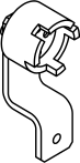
Alignment Tool, Camshaft Sprocket VM.9991A fits into place.
-
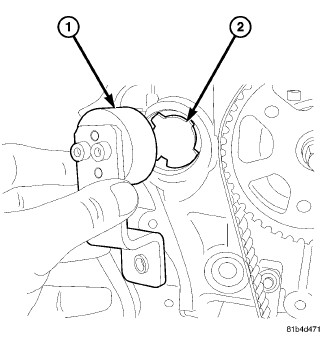
Install the
Alignment Tool, Camshaft Sprocket VM.9991A (1) onto the camshaft position sensor tone wheel (2).
-
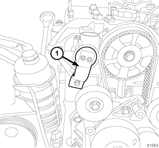
When the
Alignment Tool, Camshaft Sprocket VM.9991A is bolted in place, the camshafts are locked at 90 degrees
ATDC.
-
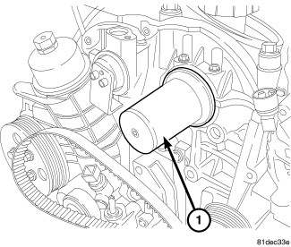
Using the
Installer, Seal 9937-1 and
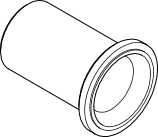
Guide, Seal 9937-2 (1), install the intake camshaft oil seal.
-
Install the cylinder
head cover (7) (Refer to 09
- Engine/Cylinder Head/COVER(S)
, Cylinder Head - Installation).
- Install the camshaft sprocket (2) (Refer to 09 - Engine/Valve Timing/SPROCKET(S) , Timing Belt and Chain - Installation).
-
Connect the negative
battery cable.
CHECKING CAMSHAFT ENDPLAY
|
-
After camshafts are properly installed in cylinder head cover check end play of camshafts with a
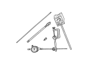
Set, Dial Indicator C-3339A . The end play should be between 0.10 mm - 0.55 mm .
NOTE: If the camshaft endplay is not within specification, replace the cylinder head.
-
Measure the camshaft end play with a
Set, Dial Indicator C-3339A . The end play should be between 0.15 mm 0.35 mm (0.006 in - 0.014 in.).