COVER(S), Cylinder Head
DESCRIPTION
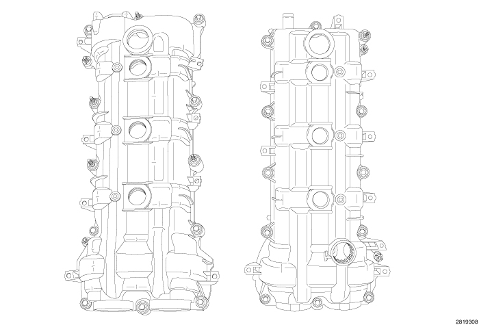 |
The cylinder head covers are made of a carbon and fiberglass composite. The cylinder head covers are not interchangable from side-to-side. The cylinder head covers are sealed with a press-in-place gasket that is designed to isolate the cover from the cylinder head for improved NVH. There are two dowel pins on the outboard side of the cover flange to locate the cover to holes in the cylinder head. RTV is used to seal the T-joint at the timing cover, cylinder head and cylinder head cover.
LEFT
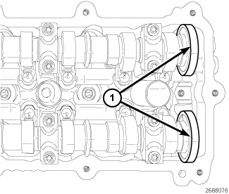 |
The magnetic timing wheels (1)
must not come in contact with magnets (pickup tools, trays, etc.)
or any other strong magnetic field. This will destroy the timing wheels
ability to correctly relay camshaft position to the camshaft position
sensor.
CAUTION:
 |
- Disconnect and isolate the negative battery cable.
-
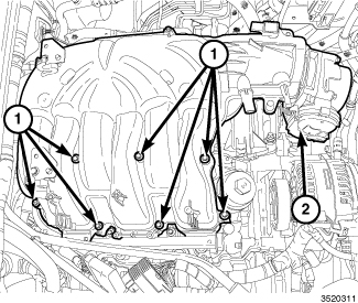
Remove the air cleaner
body and upper intake manifold (2) (Refer to 09 - Engine/Manifolds/MANIFOLD, Intake - Removal)
.
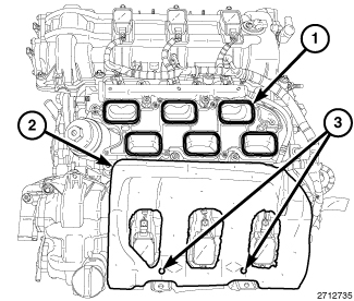
- Cover the open intake ports (1) to prevent debris from entering the engine.
-
Remove the insulator
(2) from the LH cylinder head cover.
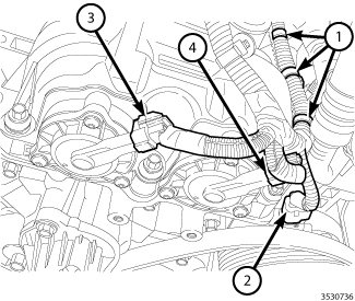
NOTE: Mark the variable valve timing solenoid connectors (3 and 4) with a paint pen or equivalent so that they may be reinstalled in their original locations.
- Disconnect the A/C compressor electrical connector (2).
- Disconnect the left exhaust variable valve timing solenoid electrical connector (4).
- Disconnect the left intake variable valve timing solenoid electrical connector (3).
-
Disengage three wire
harness retainers (1) from the left cylinder head cover.
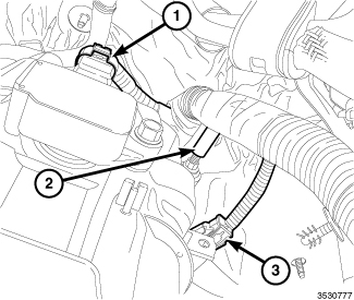
- Disconnect the Engine Coolant Temperature (ECT) sensor connector (3).
- Disconnect the left Camshaft Position (CMP) sensor (1).
-
Disengage the main
wire harness retainer (2) from the cylinder head cover mounting stud.
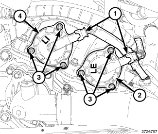
- Mark the variable valve timing solenoids (2 and 4) with a paint pen or equivalent so that they may be reinstalled in their original locations.
-
Remove the variable
valve timing solenoids
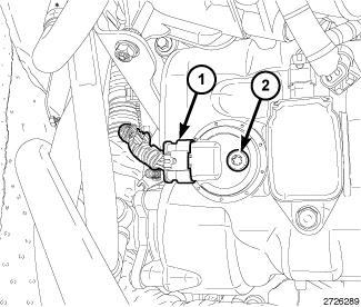
NOTE: The RH CMP sensor is shown, the LH CMP sensor is similar. If removing both RH and LH CMP sensors, mark the sensors so they can be installed in their original locations.
-
Remove the camshaft
position sensor (Refer to 08
- Electrical/8I - Ignition Control/SENSOR, Camshaft Position - Removal)
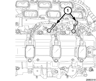
-
Disengage two injection/ignition
harness retainers (1) from the left cylinder head cover.
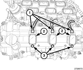
-
Remove the ignition
coils (2) (Refer to 08 - Electrical/8I
- Ignition Control/COIL, Ignition - Removal)
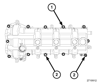
-
Loosen ten cylinder
head cover mounting bolts (1) and two studbolts (2) and remove the
cylinder head cover.
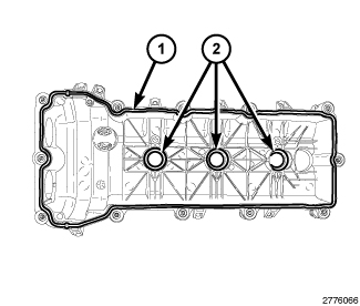
- Remove and discard the cylinder head cover gasket (1).
-
The spark plug tube
seals (2) can be reused if not damaged.
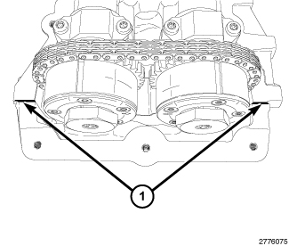
CAUTION: Do not use oil based liquids, wire brushes, abrasive wheels or metal scrapers to clean the engine gasket surfaces. Use only isopropyl (rubbing) alcohol, along with plastic or wooden scrapers. Improper gasket surface preparation may result in engine fluid leakage.
-
Remove all residual
sealant (1) from the cylinder head, timing chain cover and cylinder
head cover mating surfaces (Refer
to 09 - Engine - Standard Procedure)
RIGHT
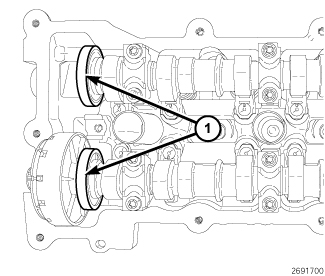 |
The magnetic timing wheels (1)
must not come in contact with magnets (pickup tools, trays, etc.)
or any other strong magnetic field. This will destroy the timing wheels
ability to correctly relay camshaft position to the camshaft position
sensor.
CAUTION:
|
- Disconnect and isolate the negative battery cable.
-
Remove the air cleaner
body and upper intake manifold (2) (Refer to 09 - Engine/Manifolds/MANIFOLD, Intake - Removal)
.
-
Cover the open intake
ports (1) to prevent debris from entering the engine.
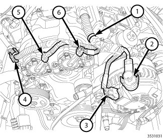
NOTE: Mark the variable valve timing solenoid connectors (5 and 6) with a paint pen or equivalent so that they may be reinstalled in their original locations.
- Disconnect the right exhaust variable valve timing solenoid electrical connector (5).
- Disconnect the right intake variable valve timing solenoid electrical connector (6).
-
Disengage the wire
harness retainers (1 and 4) from the right cylinder head cover.
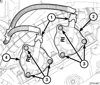
- Mark the variable valve timing solenoids (2 and 4) with a paint pen or equivalent so that they may be reinstalled in their original locations.
-
Remove the variable
valve timing solenoids
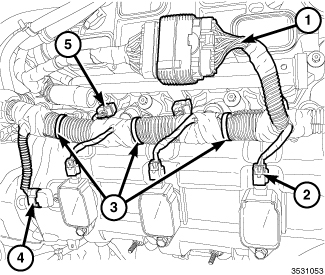
- Disconnect three ignition coil electrical connectors (2).
- Disconnect the electrical connector (4) from the right Camshaft Position (CMP) sensor.
-
Disengage three main
wire harness retainers (3) from the right cylinder head cover.
NOTE: If removing both RH and LH CMP sensors, mark the sensors so they can be installed in their original locations.
-
Remove the camshaft
position sensor (Refer to 08
- Electrical/8I - Ignition Control/SENSOR, Camshaft Position - Removal)
NOTE: The LH ignition coils are shown, the RH ignition coils are similar.
-
Remove the ignition
coils (2) (Refer to 08 - Electrical/8I
- Ignition Control/COIL, Ignition - Removal)
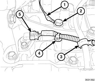
- Raise and support the vehicle (Refer to 04 - Vehicle Quick Reference/Hoisting - Standard Procedure) .
-
Disengage the main
wire harness retainer (3) from the oil level indicator.
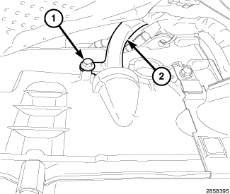
-
Loosen the bolt (1)
securing the transmission fluid level indicator tube (2) to the transmission
housing.
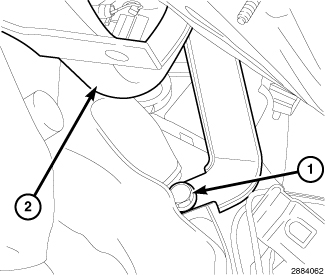
-
Remove the upper transmission
to engine bolt (1) and reposition the transmission oil level indicator
tube (2).
- Lower the vehicle.
-
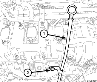
Remove the bolt (2)
and the oil level indicator (1).
-
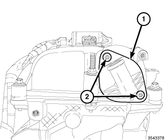
Remove the PCV valve
(1) (Refer to 25 - Emissions
Control/Evaporative Emissions/VALVE, Positive Crankcase Ventilation
(PCV)
- Removal)
-
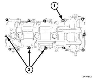
Loosen nine cylinder
head cover mounting bolts (1) and three studbolts (2) and remove the
cylinder head cover.
NOTE: The LH cylinder head cover is shown, the RH cylinder head cover is similar.
- Remove and discard the cylinder head cover gasket (1).
-
The spark plug tube
seals (2) can be reused if not damaged.
NOTE: The LH cylinder head cover T-joints are shown, the RH cylinder head cover T-joints are similar.
CAUTION: Do not use oil based liquids, wire brushes, abrasive wheels or metal scrapers to clean the engine gasket surfaces. Use only isopropyl (rubbing) alcohol, along with plastic or wooden scrapers. Improper gasket surface preparation may result in engine fluid leakage.
-
Remove all residual
sealant (1) from the cylinder head, timing chain cover and cylinder
head cover mating surfaces (Refer
to 09 - Engine - Standard Procedure)
LEFT
|
The magnetic timing wheels (1)
must not come in contact with magnets (pickup tools, trays, etc.)
or any other strong magnetic field. This will destroy the timing wheels
ability to correctly relay camshaft position to the camshaft position
sensor.
CAUTION:
|
- Install the cylinder head cover gasket (1).
-
The spark plug tube
seals (2) can be reused if not damaged.
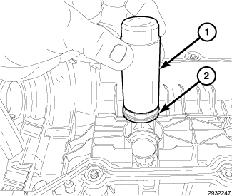
-
If required, install
new spark plug tube seals (2) in the cylinder head cover:
- Lubricate the spark plug tube seal inner and outer diameters with clean engine oil.
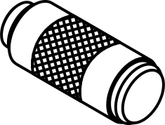
- Place the spark plug tube seal (2) on the Cam Sensor/Spark Plug Tube Seal Installer 10256 (1).
- Push the seal into the cylinder head cover until the base of the seal is seated.
-
Remove the tool.
-
Clean the timing engine
timing cover, cylinder head and cylinder head cover mating surfaces
with isopropyl alcohol in preparation for sealant application.
CAUTION: Engine assembly requires the use of a unique sealant that is compatible with engine oil. Using a sealant other than Mopar® Threebond Engine RTV Sealant may result in engine fluid leakage.
CAUTION: Following the application of Mopar® Threebond Engine RTV Sealant to the gasket surfaces, the components must be assembled within 20 minutes and the attaching fasteners must be tightened to specification within 45 minutes. Prolonged exposure to the air prior to assembly may result in engine fluid leakage.
-
Apply a 2 to 3 mm wide
bead of Mopar® Threebond Engine RTV Sealant (1) to the two engine
timing cover to cylinder head T-joints as shown.
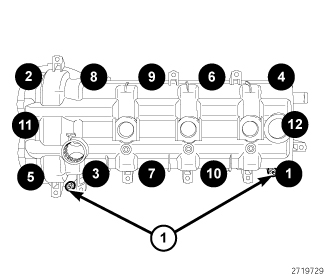
- Align the locator pins (1) to the cylinder head and install the cylinder head cover.
-
Tighten the cylinder
head cover bolts and double ended studs in the sequence shown to 12
N·m (106 in. lbs.).
- If removed, install the spark plugs (Refer to 08 - Electrical/8I - Ignition Control/SPARK PLUG - Installation)
-
Install the ignition
coils (Refer to 08 - Electrical/8I
- Ignition Control/COIL, Ignition - Installation)
-
Engage two injection/ignition
harness retainers (1) to the left cylinder head cover.
-
Refer to the markings
made at disassembly and install the variable valve timing solenoids
(2 and 4) in their original locations
- Connect the A/C compressor electrical connector (2).
- Connect the left exhaust variable valve timing solenoid electrical connector (4).
- Connect the left intake variable valve timing solenoid electrical connector (3).
-
Engage three wire harness
retainers (1) to the left cylinder head cover.
NOTE: The RH CMP sensor is shown, the LH CMP sensor is similar. If both RH and LH CMP sensors where removed, install them into their original locations.
-
Install the camshaft
position sensor (Refer to 08
- Electrical/8I - Ignition Control/SENSOR, Camshaft Position - Installation)
- Connect the Engine Coolant Temperature (ECT) sensor connector (3).
- Connect the left Camshaft Position (CMP) sensor (1).
-
Engage the main wire
harness retainer (2) to the cylinder head cover mounting stud.
-
Install the insulator
(2) to the two alignment posts (3) on top of the LH cylinder head
cover.
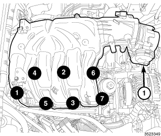
- Install the upper intake manifold (1), support brackets and air cleaner body (Refer to 09 - Engine/Manifolds/MANIFOLD, Intake - Installation)
- Connect the negative battery cable and tighten nut to 5 N·m (45 in. lbs.).
| NOTE: |
The Cam/Crank Variation
Relearn procedure must be performed using the scan tool anytime there
has been a repair/replacement made to a powertrain system, for example:
flywheel, valvetrain, camshaft and/or crankshaft sensors or components. |
RIGHT
|
The magnetic timing wheels (1)
must not come in contact with magnets (pickup tools, trays, etc.)
or any other strong magnetic field. This will destroy the timing wheels
ability to correctly relay camshaft position to the camshaft position
sensor.
CAUTION:
|
| NOTE: |
The LH cylinder head cover is shown, the RH cylinder head cover is similar. |
- Install the cylinder head cover gasket (1).
-
The spark plug tube
seals (2) can be reused if not damaged.
-
If required, install
new spark plug tube seals (2) in the cylinder head cover:
- Lubricate the spark plug tube seal inner and outer diameters with clean engine oil.
- Place the spark plug tube seal (2) on the Cam Sensor/Spark Plug Tube Seal Installer 10256 (1).
- Push the seal into the cylinder head cover until the base of the seal is seated.
-
Remove the tool.
NOTE: The LH cylinder head cover T-joint is shown, the RH cylinder head cover T-joint is similar.
-
Clean the timing engine
timing cover, cylinder head and cylinder head cover mating surfaces
with isopropyl alcohol in preparation for sealant application.
CAUTION: Engine assembly requires the use of a unique sealant that is compatible with engine oil. Using a sealant other than Mopar® Threebond Engine RTV Sealant may result in engine fluid leakage.
CAUTION: Following the application of Mopar® Threebond Engine RTV Sealant to the gasket surfaces, the components must be assembled within 20 minutes and the attaching fasteners must be tightened to specification within 45 minutes. Prolonged exposure to the air prior to assembly may result in engine fluid leakage.
-
Apply a 2 to 3 mm wide
bead of Mopar® Threebond Engine RTV Sealant (1) to the two engine
timing cover to cylinder head T-joints as shown.
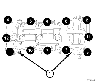
- Align the locator pins (1) to the cylinder head and install the cylinder head cover.
-
Tighten the cylinder
head cover bolts and double ended studs in the sequence shown to 12
N·m (106 in. lbs.).
NOTE: The LH ignition coils are shown, the RH ignition coils are similar.
- If removed, install the spark plugs (Refer to 08 - Electrical/8I - Ignition Control/SPARK PLUG - Installation)
-
Install the ignition
coils (2) (Refer to 08 - Electrical/8I
- Ignition Control/COIL, Ignition - Installation)
-
Refer to the markings
made at disassembly and install the variable valve timing solenoids
(2 and 4) in their original locations
- Connect the right exhaust variable valve timing solenoid electrical connector (5).
- Connect the right intake variable valve timing solenoid electrical connector (6).
-
Engage the wire harness
retainers (1 and 4) to the right cylinder head cover.
NOTE: If both RH and LH CMP sensors where removed, install them into their original locations.
-
Install the camshaft
position sensor (Refer to 08
- Electrical/8I - Ignition Control/SENSOR, Camshaft Position - Installation)
- Connect three ignition coil electrical connectors (2).
- Connect the electrical connector (4) to the right Camshaft Position (CMP) sensor.
-
Engage three main wire
harness retainers (3) to the right cylinder head cover.
-
Install the PCV valve
(1) (Refer to 25 - Emissions
Control/Evaporative Emissions/VALVE, Positive Crankcase Ventilation
(PCV)
- Removal)
-
Install the oil level
indicator (1) with the bolt (2) tightened to 12 N·m (106 in. lbs.).
- Raise and support the vehicle (Refer to 04 - Vehicle Quick Reference/Hoisting - Standard Procedure) .
-
Install the transmission
oil level indicator tube (2) with the upper transmission to engine
bolt (1) tightened to 55 N·m (41 ft. lbs.).
-
Install the bolt (1)
securing the transmission fluid level indicator tube (2) to the transmission
housing and tighten to 12 N·m (106 in. lbs.).
-
Engage the main wire
harness retainer (3) to the oil level indicator.
- Lower the vehicle.
-
If removed, install
the insulator (2) to the two alignment posts (3) on top of the LH
cylinder head cover.
- Install the upper intake manifold (1), support brackets and air cleaner body (Refer to 09 - Engine/Manifolds/MANIFOLD, Intake - Installation)
- Connect the negative battery cable and tighten nut to 5 N·m (45 in. lbs.).
| NOTE: |
The Cam/Crank Variation
Relearn procedure must be performed using the scan tool anytime there
has been a repair/replacement made to a powertrain system, for example:
flywheel, valvetrain, camshaft and/or crankshaft sensors or components. |