LIFTER(S), Hydraulic
DIAGNOSIS AND TESTING - HYDRAULIC LIFTER(S) NOISE DIAGNOSIS
Proper noise diagnosis is essential in locating the source of an NVH complaint. Locating a lash adjuster (tappet) type noise can sometimes be difficult. As a result, an initial misdiagnosis may occur.
Refer to the following chart for possible causes and correction of a lash adjuster (tappet) type noise.
LASH ADJUSTER (TAPPET) NOISE CHART
|
POSSIBLE CAUSES |
CORRECTION |
|---|---|
|
1. Engine oil level—too high or too low. This may allow aerated oil to enter the adjusters and cause them to be spongy. |
1. Check and correct the engine oil level. |
|
2. Insufficient running time after rebuilding a cylinder head. |
2. Low speed running of up to 1 hour may be required to fully evacuate trapped air from the valve train system. During this time, turn engine off and let set for a few minutes before restarting. Repeat this several times after engine has reached normal operating temperature. |
|
3. Air trapped in the lash adjuster (after 1 hour of run time). |
3. See below: |
|
(a) Check lash adjusters for sponginess while installed in the cylinder head. Depress the rocker arm over the adjuster. Normal adjusters should feel very firm. Very spongy adjusters can be bottomed out easily. |
|
|
(b) If the lash adjuster(s) are still spongy, replace the lash adjuster(s) (Refer to 09 - Engine/Cylinder Head/LIFTER(S) , Hydraulic - Removal). |
|
|
4. Low oil pressure. |
4. See below: |
|
(a) Check and correct the engine oil level. |
|
|
(b) Check the engine oil pressure (Refer to 09 - Engine/Lubrication - Diagnosis and Testing) . |
|
|
(c) Check for excessive main bearing clearance and correct (Refer to 09 - Engine/Engine Block/BEARING(S) , Crankshaft - Standard Procedure). |
|
|
(d) Check for a worn oil pump (Refer to 09 - Engine/Lubrication/PUMP, Engine Oil - Inspection) . |
|
|
5. Oil passage to the cylinder head(s) plugged with debris. |
5. Check cylinder head oil passages for blockage. Clean or replace as necessary. |
|
6. Worn valve guide(s). |
6. Measure valve stem-to-guide clearance (Refer to 09 - Engine/Cylinder Head/VALVES, Intake and Exhaust - Inspection) . |
|
7. Air ingested into oil due to broken or cracked oil pump pickup tube. |
7. Inspect pickup tube and replace as necessary (Refer to 09 - Engine/Lubrication/PICK-UP, Oil Pump - Removal) . |
|
8. Collapsed lash adjuster due to debris ingestion. |
8. Clean debris from engine and replace lash adjuster(s) (Refer to 09 - Engine/Cylinder Head/LIFTER(S) , Hydraulic - Removal). |
REMOVAL
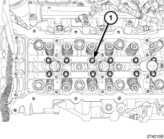 |
| NOTE: |
The LH cylinder head hydraulic lifters are shown, the RH cylinder head hydraulic lifters are similar. |
- Disconnect and isolate the negative battery cable.
-
Remove the camshaft(s) (Refer to 09 - Engine/Cylinder Head/CAMSHAFT, Engine - Removal)
NOTE: If the rocker arms are to be reused, identify their positions so that they can be reassembled into their original locations.
-
Remove the rocker arm(s) (Refer to 09 - Engine/Cylinder Head/ROCKER ARM, Valve - Removal)
NOTE: If the hydraulic lifters are to be reused, identify their positions so that they can be reassembled into their original locations.
-
Remove the hydraulic lifter(s) (1).
INSTALLATION
|
| NOTE: |
The LH cylinder head hydraulic lifters are shown, the RH cylinder head hydraulic lifters are similar. If the hydraulic lifters are being reused, reassemble them into their original locations. |
- Verify that the hydraulic lifters are at least partially full of oil. There should be little or no plunger travel when the hydraulic lifter is depressed.
-
Install the hydraulic lifter(s) (1).
NOTE: If the rocker arms are being reused, reassemble them into their original locations.
- Install the rocker arm(s) (Refer to 09 - Engine/Cylinder Head/ROCKER ARM, Valve - Installation) .
- Install the camshaft(s), phasers, cylinder head cover(s) and upper intake manifold (Refer to 09 - Engine/Cylinder Head/CAMSHAFT, Engine - Installation)
-
Connect the negative battery cable and tighten nut to 5 N·m (45 in. lbs.).