SPRING(S), Valve
DESCRIPTION
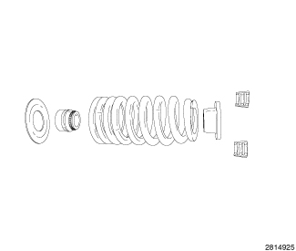 |
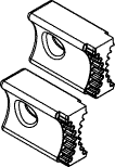
The valve springs are a beehive design and made from high strength chrome silicon steel. The springs are common for intake and exhaust applications. Valve guide seals are rubber overmolded on a steel support cylinder with a garter spring at the seal lip. The seals are not integrated with the valve spring seat. The valve spring seat is a flat steel washer. The steel valve spring retainers are designed for use with beehive springs and the valve spring retainer locks are a three bead Butt type design.
IN VEHICLE
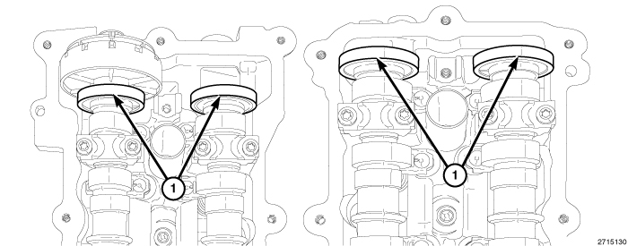 |
The magnetic timing wheels (1)
must not come in contact with magnets (pickup tools, trays, etc.)
or any other strong magnetic field. This will destroy the timing wheels
ability to correctly relay camshaft position to the camshaft position
sensor.
CAUTION:
 |
- Disconnect and isolate the negative battery cable.
-
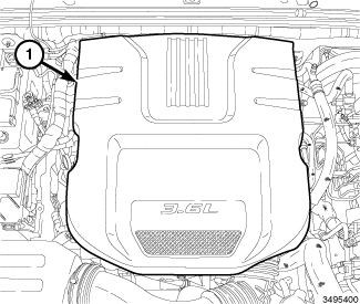
Remove the engine cover (1).
-
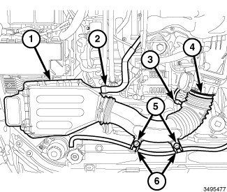
Remove the air cleaner body (1) (Refer to 09 - Engine/Air Intake System/BODY, Air Cleaner - Removal)
.
-
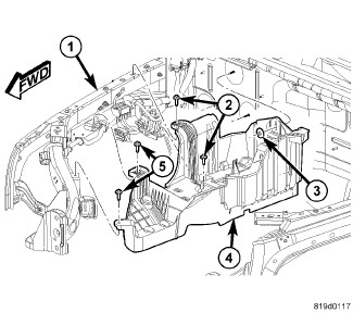
If removing the RH valve springs, remove the battery, Totally Integrated Power Module (TIPM) and battery tray (4) (Refer to 08 - Electrical/8F - Engine Systems/Battery System/TRAY, Battery - Removal)
.
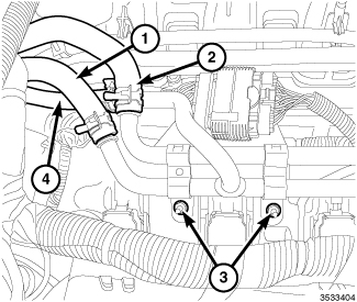
- If removing the RH valve springs, drain the cooling system (Refer to 07 - Cooling - Standard Procedure) .
- If removing the RH valve springs, remove the heater core supply hose (2), heater core return hose (1) and oil cooler return hose (4) from the heater core tube assembly.
-
If removing the RH valve springs, remove two nuts (3) and reposition the heater core tube assembly to the front of the engine.
-
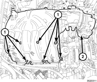
Remove the upper intake manifold (2) and both cylinder head covers (Refer to 09 - Engine/Cylinder Head/COVER(S)
, Cylinder Head - Removal)
-
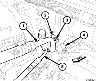
If removing the LH exhaust valve springs, recover the refrigerant from the refrigerant system and remove the A/C suction and liquid line assembly (1 and 5) (Refer to 24 - Heating and Air Conditioning/Plumbing/LINE, A/C Suction - Removal)
.
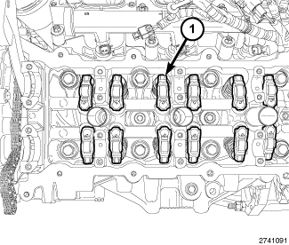
NOTE: The LH cylinder head rocker arms are shown, the RH cylinder head rocker arms are similar.
NOTE: Only remove the camshafts from one head at a time. The opposite head must remain assembled in order to lock the crankshaft against rotation.
-
Remove the camshaft(s) (Refer to 09 - Engine/Cylinder Head/CAMSHAFT, Engine - Removal)
.
NOTE: If the rocker arms are to be reused, identify their positions so that they can be reassembled into their original locations.
-
Remove the rocker arm(s) (1) (Refer to 09 - Engine/Cylinder Head/ROCKER ARM, Valve - Removal)
.
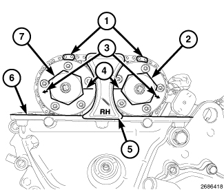
NOTE: RH camshaft phaser lock shown, LH camshaft phaser lock similar.
CAUTION: Air pressure applied to the cylinder holds the valves in place. This air pressure also has a tendency to force the piston down and rotate the crankshaft. Do not allow the crankshaft to rotate. Crankshaft rotation may damage the timing chain or front timing cover and affect camshaft timing.
-
If removing the LH camshafts, install the RH Camshaft Phaser Lock 10202 (5) to lock the crankshaft against rotation. If removing the RH camshafts, install the LH Camshaft Phaser Lock 10202 to lock the crankshaft against rotation.
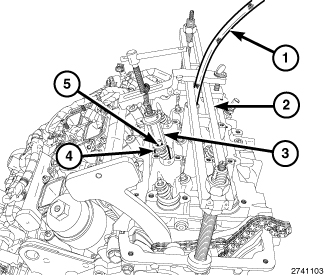
NOTE: Number 4 cylinder intake valve spring compression shown, all other valves similar.
- Remove the spark plug (Refer to 08 - Electrical/8I - Ignition Control/SPARK PLUG - Removal) .
- Install Valve Spring Compressor MD998772A (2) onto the cylinder head.
-
Install a spark plug adapter attached to a regulated shop air supply (1). Pressurize the cylinder being serviced to 620.5 - 689 kPa (90 - 100 psi) to hold the valves in place.
CAUTION: Air pressure must be maintained as long as the valve springs are removed to prevent the valves from dropping into the cylinders.
-
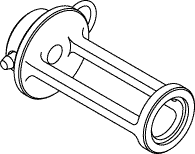
Using Valve Spring Compressor Adapter 10224 (3), compress valve spring (4) and remove valve retaining locks (5).
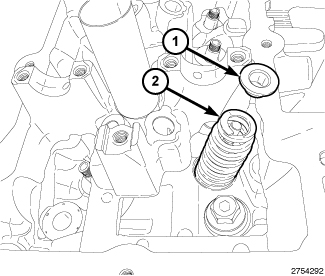
NOTE: If the springs are to be reused, identify their positions so that they can be reassembled into their original locations. Number 5 cylinder exhaust valve spring shown, all other valve springs similar.
- Release the valve spring compression and remove the valve spring retainer (1) and valve spring (2).
-
If required, remove the valve guide seal and spring seat (Refer to 09 - Engine/Cylinder Head/SEAL(S)
, Valve Guide - Removal).
OFF VEHICLE
 |
- Remove the cylinder head(s) (Refer to 09 - Engine/Cylinder Head - Removal)
-
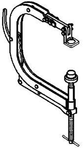
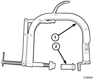
Position the Valve Spring Compressor Adapter 10224 (2) in the Valve Spring Compressor C-3422-D (1).
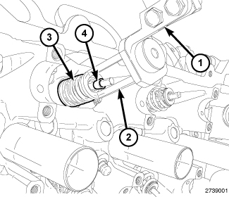
NOTE: Number 3 cylinder intake valve spring compression shown, all other valves similar.
-
Compress the valve spring (3) and remove the valve retaining locks (4).
NOTE: If the springs are to be reused, identify their positions so that they can be reassembled into their original locations. Number 5 cylinder exhaust valve spring shown, all other valves similar.
- Release the valve spring compression and remove the valve spring retainer (1) and valve spring (2).
- If required, remove the valve(s) (Refer to 09 - Engine/Cylinder Head/VALVES, Intake and Exhaust - Removal)
-
If required, remove the valve guide seal and spring seat (Refer to 09 - Engine/Cylinder Head/SEAL(S)
, Valve Guide - Removal).
INSPECTION
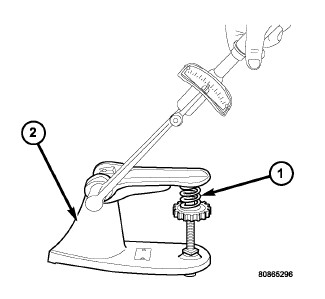 |
When valves have been removed for inspection, reconditioning or replacement, valve springs should be checked against specifications for free-length, spring force and spring installed height (Refer to 09 - Engine - Specifications) .
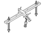
Spring force can be measured with a test fixture (2). Follow the tool manufactures instructions. Replace any springs that do not meet specifications.
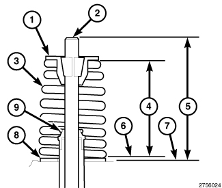 |
Installed height of the valve spring must be checked with the valve assembled into the cylinder head (Refer to 09 - Engine/Cylinder Head/SPRING(S) , Valve - Installation).
If the valves or valve seats have been refinished and the installed valve spring height (4) is greater than 40.0 mm (1.575 in.), install an additional spring seat (8) in the head counterbore under the original valve spring seat (8) to bring the spring height back within specification. Make sure the measurement is taken from the top of spring seat (6) to the bottom surface of spring retainer (1).
IN VEHICLE
 |
-
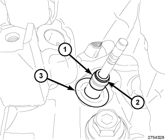
If removed, install the spring seat (3) and valve guide seal (1) over the valve guide (Refer to 09 - Engine/Cylinder Head/SEAL(S)
, Valve Guide - Installation)
NOTE: Ensure that the garter spring (2) is intact around the top of the valve guide seal (1). Number 5 cylinder exhaust valve guide seal shown, all other valves similar.
NOTE: If the valve springs are being reused, reassemble them into their original locations. Number 5 cylinder exhaust valve spring shown, all other valves similar.
-
Install the valve spring (2) and valve spring retainer (1).
NOTE: Number 4 cylinder intake valve spring compression shown, all other valves similar.
- Using Valve Spring Compressor Adapter 10224 (3) with Valve Spring Compressor MD998772A (2), compress the valve spring (4) only enough to install the valve retaining locks (5).
- Relieve the air pressure and remove the spark plug adapter.
-
Install the spark plug and tighten to 17.5 N·m (13 ft. lbs.) (Refer to 08 - Electrical/8I - Ignition Control/SPARK PLUG - Installation)
.
NOTE: The LH cylinder head rocker arms are shown, the RH cylinder head rocker arms are similar. If the rocker arms are being reused, reassemble them into their original locations.
-
Install the rocker arm(s) (1) and camshaft(s) (Refer to 09 - Engine/Cylinder Head/ROCKER ARM, Valve - Installation)
.
-
If removed, install the A/C suction and liquid line assembly (1 and 5) (Refer to 24 - Heating and Air Conditioning/Plumbing/LINE, A/C Suction - Installation)
.
-
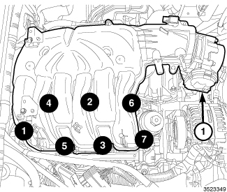
Install the cylinder head cover(s) and upper intake manifold (1) (Refer to 09 - Engine/Cylinder Head/CAMSHAFT, Engine - Installation)
- If removed, position the heater core tube assembly and install the heater core supply hose (2), heater core return hose (1) and oil cooler return hose (4).
-
Secure the heater core tube assembly to the right upper intake manifold support bracket with two nuts (3) tightened to 12 N·m (106 in. lbs.).
-
If removed, install the battery tray (4), Totally Integrated Power Module (TIPM) and battery (Refer to 08 - Electrical/8F - Engine Systems/Battery System/TRAY, Battery - Installation)
.
-
Install the air cleaner body (1) (Refer to 09 - Engine/Air Intake System/BODY, Air Cleaner - Installation)
.
- If removed, install the oil filter and fill the engine crankcase with the proper oil to the correct level (Refer to 09 - Engine/Lubrication/OIL - Standard Procedure)
- Fill the cooling system (Refer to 07 - Cooling - Standard Procedure) .
- Install the engine cover (1).
- Connect the negative battery cable and tighten nut to 5 N·m (45 in. lbs.).
- Run the engine until it reaches normal operating temperature. Check cooling system for correct fluid level (Refer to 07 - Cooling - Standard Procedure)
| NOTE: |
The Cam/Crank Variation Relearn procedure must be performed using the scan tool anytime there has been a repair/replacement made to a powertrain system, for example: flywheel, valvetrain, camshaft and/or crankshaft sensors or components. |
OFF VEHICLE
|
-
If removed, install the valve(s) (Refer to 09 - Engine/Cylinder Head/VALVES, Intake and Exhaust - Installation)
.
NOTE: Reassemble the valves into their original locations. If the valves or valve seats have been refinished, verify that the valve stem tip height is within specification (Refer to 09 - Engine - Specifications) . Number 5 cylinder exhaust valve shown, all other valves similar.
-
If removed, install the spring seat (3) and valve guide seal (1) over the valve guide (Refer to 09 - Engine/Cylinder Head/SEAL(S)
, Valve Guide - Installation).
NOTE: Ensure that the garter spring (2) is intact around the top of the valve guide seal (1). Number 5 cylinder exhaust valve guide seal shown, all other valves similar.
NOTE: If the valve springs are being reused, reassemble them into their original locations. Number 5 cylinder exhaust valve spring shown, all other valves similar.
-
Install the valve spring (2) and valve spring retainer (1).
NOTE: Number 3 cylinder intake valve spring compression shown, all other valves similar.
-
Compress valve springs (3) with the Valve Spring Compressor Adapter 10224 (2) mounted in the Valve Spring Compressor C-3422-D (1). Install the retaining locks (4) and release the valve spring compression.
- If the valves or valve seats have been refinished, check the installed height of the valve springs (4). If the installed valve spring height (4) is greater than 40.0 mm (1.575 in.), install an additional spring seat (8) in the head counterbore under the original valve spring seat (8) to bring the spring height back within specification. Make sure the measurement is taken from the top of spring seat (6) to the bottom surface of spring retainer (1).
-
Install the cylinder head(s) (Refer to 09 - Engine/Cylinder Head - Installation)