DUCT, Instrument Panel, Assembly
REMOVAL
Disable the airbag system before
attempting any steering wheel, steering column or instrument panel
component diagnosis or service. Disconnect and isolate the negative
battery (ground) cable, then wait two minutes for the airbag system
capacitor to discharge before performing further diagnosis or service.
This is the only sure way to disable the airbag system. Failure to
follow these instructions may result in accidental airbag deployment
and possible serious or fatal injury.
WARNING:
| NOTE: |
Take the proper precautions to protect the face of the instrument panel from cosmetic damage while performing this procedure. |
| NOTE: |
LHD model shown in illustrations. RHD model similar. |
 |
- Disconnect and isolate the negative battery cable.
- Remove the radio (Refer to 08 - Electrical/8A - Audio and Video/RADIO - Removal) .
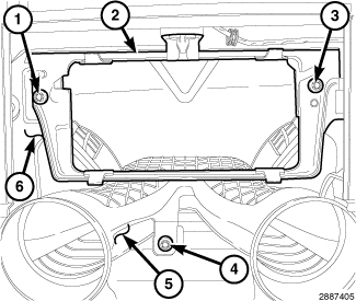
- Remove the two screws (1 and 3) that secure the radio bracket (2) to the instrument panel support (6).
- Remove the radio bracket from the instrument panel.
-
Remove the screw (4) that secures the instrument panel duct assembly (5) to the instrument panel support.
- Remove the instrument panel and place it on a workbench (Refer to 23 - Body/Instrument Panel/PANEL, Instrument - Removal) .
-
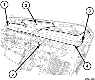
Remove the three screws (1, 2 and 3) that secure the instrument panel duct assembly (4) to the instrument panel support (5).
NOTE: If the foam seal on a duct, outlet or top of HVAC housing is deformed or damaged, the seal must be replaced.
-
Carefully remove the instrument panel duct assembly from the instrument panel.
INSTALLATION
| NOTE: |
Take the proper precautions to protect the face of the instrument panel from cosmetic damage while performing this procedure. |
| NOTE: |
LHD model shown in illustrations. RHD model similar. |
|
| NOTE: |
If the foam seal on a duct, outlet or top of HVAC housing is deformed or damaged, the seal must be replaced. |
- Position the instrument panel duct assembly (4) into the instrument panel. Be sure that all duct connections are correctly made and that the foam seals are not damaged or deformed.
-
Install the three screws (1, 2 and 3) that secure the instrument panel duct assembly to the instrument panel support (5). Tighten the screws to 1.2 N·m (10 in. lbs.).
- Install the instrument panel (Refer to 23 - Body/Instrument Panel/PANEL, Instrument - Installation) .
- Install the screw (4) that secures the instrument panel duct assembly (5) to the instrument panel support (6). Tighten the screw to 1.2 N·m (10 in. lbs.).
- Position the radio bracket (2) onto the instrument panel support.
- Install the two screws (1 and 3) that secure the radio bracket to the instrument panel support. Tighten the screws to 2 N·m (17 in. lbs.).
- Install the radio (Refer to 08 - Electrical/8A - Audio and Video/RADIO - Installation) .
-
Reconnect the negative battery cable.