CRANKSHAFT
DESCRIPTION
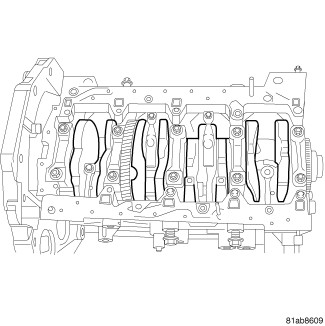 |
The crankshaft for the 2.8L is a forged steel type design with five main bearing journals. The crankshaft is located at the bottom of the engine block.
STANDARD PROCEDURE
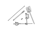
Special Tools: Click to display a list of tools used in this procedure
|
- Mount a Set, Dial Indicator C-3339A to a stationary point at rear of engine. Locate the probe perpendicular against the flywheel.
- Move the crankshaft all the way to the front of its travel.
- Zero the dial indicator.
-
Move the crankshaft all the way to the rear and read dial indicator. For crankshaft end play clearances (Refer to 09 - Engine - Specifications)
.
REMOVAL
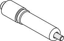
Special Tools: Click to display a list of tools used in this procedure
|
- Disconnect the negative battery cable.
- Remove the engine from vehicle (Refer to 09 - Engine - Removal) .
- On manual transmission models, remove the clutch.
- On manual transmission models, remove the flywheel.
-
Remove the flex plate.
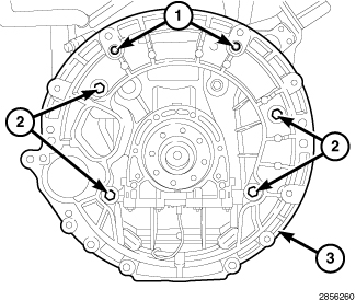
- Remove bolts (1 and 2), and the transmission adapter plate (3).
- Using a suitable engine stand, mount engine to engine stand.
- Remove the high pressure fuel tube from high pressure pump and fuel rail.
- Remove the vacuum line from vacuum pump.
- Remove the inner timing belt cover (Refer to 09 - Engine/Valve Timing/COVER(S) , Engine Timing - Removal).
- Remove the balance shaft module (Refer to 09 - Engine/Engine Block/MODULE, Balance Shaft - Removal) .
- Remove the rear crankshaft oil seal carrier (Refer to 09 - Engine/Engine Block/SEAL, Crankshaft Oil - Removal) .
- Remove the front cover and front crank oil seal (Refer to 09 - Engine/Engine Block/COVER, Engine - Removal) .
- Remove the Adapter, 90 Degree ATDC VM.9992 .
- Remove the bearing caps from the piston rods.
- Remove the bearing caps from the crankshaft journals.
-
Remove the crankshaft.
INSTALLATION
Special Tools: Click to display a list of tools used in this procedure
 |
- Clean and inspect the new crankshaft.
-
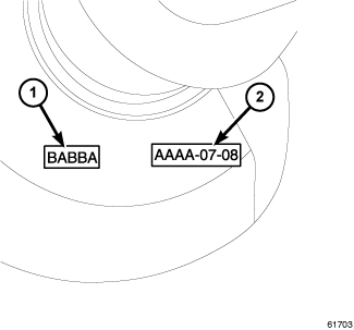
Locate the crankshaft
journal size (1) stamp on the crankshaft weight.
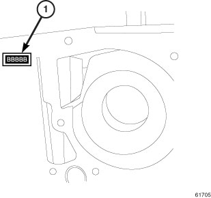
- Locate the engine block crankshaft journal size stamp on the engine block (1).
- Use the crankshaft bearing selection chart for main bearing selection (Refer to 09 - Engine/Engine Block - Standard Procedure) .
- Lubricate and install the crankshaft bearings. Make sure the thrust washer is not touching the engine block.
-
Install the crankshaft.
-
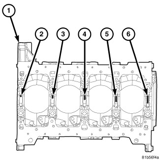
Using new bolts, install
the main bearing caps in the same location as they were removed. The
notches on the top of the bearing caps indicate their proper position.
The front cap has one notch, the next cap two, etc.
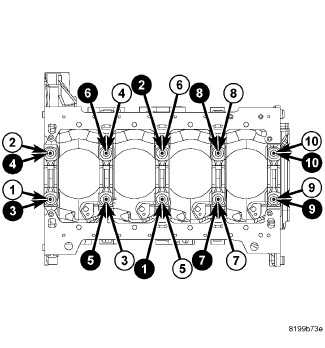
- Using the black number bubbles in the torque pattern, tighten the crankshaft bolts to 50 N·m (37 ft. lbs.).
- Using the white number bubbles in the tightening pattern, turn bolts an additional 90 degrees.
-
Using a
Set, Dial Indicator C-3339A , measure the crankshaft end play. Crankshaft end play must
be between 0.1 mm and 0.33 mm (0.004 in — 0.13 in).
- Use the connecting rod bearing selection chart for connecting rod bearing selection (Refer to 09 - Engine/Engine Block - Standard Procedure) .
- Install the connecting rod bearing caps (Refer to 09 - Engine/Engine Block/ROD, Piston and Connecting - Installation) .
- Install the front cover and front crankshaft oil seal (Refer to 09 - Engine/Engine Block/SEAL, Crankshaft Oil - Installation) .
- Install the rear crankshaft oil seal carrier (Refer to 09 - Engine/Engine Block/SEAL, Crankshaft Oil - Installation) .
- Install the balance shaft module (Refer to 09 - Engine/Engine Block/MODULE, Balance Shaft - Installation) .
- Install the inner timing belt cover (Refer to 09 - Engine/Valve Timing/COVER(S) , Engine Timing - Installation).
- Install the vacuum line onto vacuum pump.
- Install the high pressure fuel tube to high pressure pump and fuel rail and tighten to:
- Install fuel line clamp bolt. Tighten bolt to 15 N·m (133 in. lbs.).
-
Remove the engine from
engine stand.
- Install the transmission adapter plate (3). Tighten bolts:
- Install the flex plate and tighten bolts finger tight.
- Use a cross pattern to tighten bolts to 50 N·m (37 ft. lbs.).
-
Using a torque wrench
fitted with a Torque Angle Gauge, (Goniometer), loosen one flex plate
bolt at a time and tighten to 25 N·m (18 ft. lbs.) plus angle in relation
to bolt length.
Bolt Length
Torque Angle
40 mm
60°
50 mm
75°
60 mm
90°
- On manual transmission models, Using new bolts, install the flywheel. Tighten bolts to 25 N·m (18 ft. lbs.) plus angle in relation to bolt length.
- On manual transmission models, Install the clutch (Refer to 06 - Clutch/DISC, Clutch - Installation) .
- Install the engine into vehicle (Refer to 09 - Engine - Installation) .
- Connect the negative battery cable.