ROD, Piston and Connecting
DESCRIPTION
 |
Do not use a metal stamp to mark
connecting rods as damage may result, instead use ink or a scratch
awl.
CAUTION:
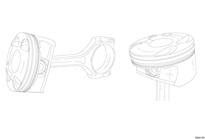
The pistons are a lightweight design with ultra low tension piston rings for improved fuel economy. The pistons are made of a high strength aluminum alloy and the piston skirt has a Moly® coating. The top piston ring land has an anodized coating for improved wear. The piston is connected to the rod using a full floating pin with two locking clips. The connecting rod is forged steel with a bolted cracked cap design. The connecting rod bolts are not reusable. Pistons are available in two different diameters with grade markings for each bore indicated on the side of the cylinder block. The upper compression ring is a 1.2 mm steel ring with a spray coating. The intermediate compression ring is 1.2 mm micro napier design. Both compression rings have a dot or a mark on the piston ring. The marked side of the ring must face the top of the piston. The 2 mm three piece oil control ring is very thin. These are chrome plated rings and have a stainless steel expander.
Piston Fitting
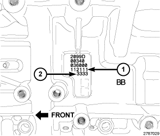 |
The pistons are “select fit” to achieve proper oil clearance. Engine
block cylinder bore diameter grade markings (1) are stamped into the
left side of the engine block. These marks are read from left to right,
corresponding with cylinder number 1, 2, 3, 4, 5, 6.
Engine block cylinder bore diameter grade markings correspond to specific cylinder bore diameters. The chart below identifies the two engine block grade markings and their associated cylinder bore diameters.
|
Engine Block Marking |
Cylinder Bore Size mm (in.) |
|---|---|
|
1 |
95.995 ± 0.005 mm (3.7793 ± 0.0002 in.) |
|
2 |
96.005 ± 0.005 mm (3.7797 ± 0.0002 in.) |
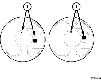 |
The piston is marked with the piston size (1 and 2) on the piston
crown. The pistons are available in two different sizes in order to
achieve the desired oil clearance. Select the piston size that corresponds
to the engine block cylinder bore diameter grade markings for each
cylinder.
Pistons are available in two sizes. The chart below identifies the two piston sizes.
|
Piston Marking |
Size mm (in.) |
|
|---|---|---|
|
Metal to Metal |
Metal to Coating |
|
|
1 |
95.995 ± 0.005 mm (3.7793 ± 0.0002 in.) |
95.970 - 96.000 mm (3.7783 - 3.7795 in.) |
|
2 |
95.965 ± 0.005 mm (3.7781 ± 0.0002 in.) |
95.980 - 96.010 mm (3.7787 - 3.7835 in.) |
 |
| NOTE: |
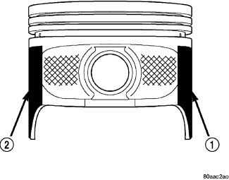
Typical coated piston shown. |
The coated pistons are serviced with the piston pin and connecting rod pre-assembled. The coating material (1 and 2) is applied to the piston after the final piston machining process. Piston installation into the cylinder bore requires slightly more pressure than that required for non-coated pistons. The bonded coating on the piston will give the appearance of a line-to-line fit with the cylinder bore.
Connecting Rod Side Clearance
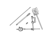
Dial Indicator
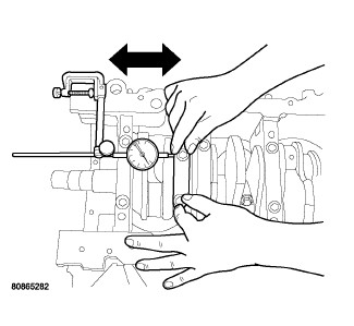 |
- Mount Dial Indicator Set C-3339A to a stationary point on the engine. Locate the probe perpendicular to and resting against the connecting rod cap being checked.
- Move the connecting rod all the way to the rear of its travel.
- Zero the dial indicator.
- Move the connecting rod forward to the limit of travel and read the dial indicator. Compare the measured side clearance to the specification (Refer to 09 - Engine - Specifications)
-
Repeat this procedure for each connecting rod. Rotate the crankshaft for connecting rod accessibility.
Feeler Gauge
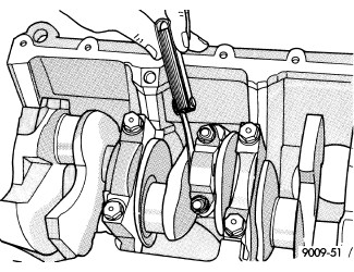 |
- Slide a snug-fitting feeler gauge between the connecting rod and crankshaft journal flange. Compare the measured side clearance to the specification (Refer to 09 - Engine - Specifications)
-
Repeat this procedure for each connecting rod. Rotate the crankshaft for connecting rod accessibility.
REMOVAL
 |
- Disconnect and isolate the negative battery cable.
- Remove the oil pans, engine timing cover and cylinder heads (Refer to 09 - Engine/Cylinder Head - Removal)
- Remove the engine oil pump (Refer to 09 - Engine/Lubrication/PUMP, Engine Oil - Removal)
-
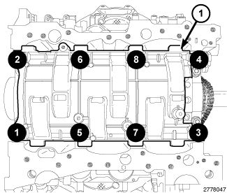
Remove the eight main bearing cap bolts from the windage tray in the sequence shown and remove the windage tray (1).
-
If necessary, remove the top ridge of the cylinder bores with a reliable ridge reamer before removing the pistons from the engine block. Be sure to keep the tops of pistons covered during this operation. Pistons and connecting rods must be removed from the top of the engine block. When removing piston and connecting rod assemblies from the engine, rotate the crankshaft CW so that each connecting rod is centered in the cylinder bore.
CAUTION: DO NOT use a number stamp or a punch to mark connecting rods or caps, as damage to connecting rods could occur
NOTE: Connecting rods and bearing caps are not interchangeable and should be marked before removing to ensure correct reassembly.
-
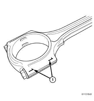
Mark connecting rod and bearing cap positions (1) using a permanent ink marker or scribe tool.
NOTE: Typical V6 engine configuration shown.
CAUTION: Care must be taken not to damage the fractured rod and cap joint face surfaces, as engine damage may occur.
-
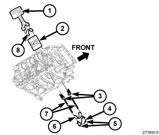
Remove the connecting rod cap bolts (5) and the connecting rod cap (4). Discard the cap bolts.
CAUTION: Care must be taken not to nick crankshaft journals, as engine damage may occur.
-
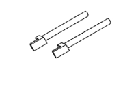
Remove the plastic guide plates (3) from the Guide Pins 8189 (7) and install the Guide Pins to the connecting rod being removed.
CAUTION: Avoid contact with the piston oil cooler jet(s). Positioning of the oil cooler jet(s) is critical for proper engine operation.
- Remove the piston and connecting rod (1) from cylinder bore.
- Repeat the previous steps for each piston being removed.
- Immediately after piston and connecting rod removal, reinstall the bearing cap (4) on the mating connecting rod to prevent damage to the fractured cap and rod surfaces.
- If required, remove the piston rings (Refer to 09 - Engine/Engine Block/RING(S) , Piston - Removal)
-
Repeat the previous steps for each piston being removed.
CLEANING
DO NOT use a wire wheel or other
abrasive cleaning devise to clean the pistons or connecting rods.
The pistons have a Moly coating, this coating must not be damaged.
CAUTION:
Do not remove the piston pin from
the piston and connecting rod assembly.
CAUTION:
INSPECTION
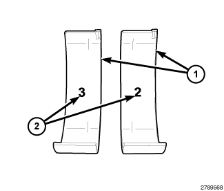 |
- Wipe the inserts (1) clean.
- Inspect the inserts for abnormal wear patterns, scoring, grooving, fatigue, pitting and for metal or other foreign material imbedded in the lining.
- Inspect the back of the inserts for fractures, scrapes, or irregular wear patterns.
- Inspect the insert locking tabs for damage.
-
Replace any bearing that shows abnormal wear (Refer to 09 - Engine/Engine Block/BEARING(S)
, Connecting Rod - Standard Procedure)
-
Inspect the connecting rod bearing bores for signs of scoring, nicks and burrs.
NOTE: Misaligned or bent connecting rods can cause abnormal wear on pistons, piston rings, cylinder walls, connecting rod bearings and crankshaft connecting rod journals. If wear patterns or damage to any of these components indicate the probability of a misaligned connecting rod, inspect it for correct rod alignment.
-
Replace misaligned, bent or twisted connecting rods.
NOTE: Connecting rods are serviced with the piston pre-assembled. The pistons are "select fit" to achieve proper oil clearance (Refer to 09 - Engine/Engine Block/ROD, Piston and Connecting - Standard Procedure)
NOTE: Typical coated piston shown.
- Inspect the piston for scoring or scraping marks in the piston skirts. Check the ring lands for cracks and/or deterioration.
-
Check the piston for taper and out of round shape.
NOTE: The coating material (1 and 2) is applied to the piston after the final piston machining process. Measuring the outside diameter of a coated piston will not provide accurate results. Therefore measuring the inside diameter of the cylinder bore with a dial Bore Gauge is MANDATORY (Refer to 09 - Engine/Engine Block - Inspection) .
- Compare the measured cylinder bore diameter to the engine block cylinder bore grade marking chart (Refer to 09 - Engine/Engine Block/ROD, Piston and Connecting - Standard Procedure) Select the piston size that corresponds to the engine block markings for each cylinder to provide the proper oil clearance.
| NOTE: |
Piston installation into the cylinder bore requires slightly more pressure than that required for non-coated pistons. The bonded coating on the piston will give the appearance of a line-to-line fit with the cylinder bore. |
| NOTE: |
The coated pistons will be serviced with the piston pin and connecting rod pre-assembled. |
INSTALLATION

 |
- If required, select and fit new piston and connecting rod assemblies to the engine block (Refer to 09 - Engine/Engine Block/ROD, Piston and Connecting - Standard Procedure)
- If required, select and fit new bearings to the connecting rod (Refer to 09 - Engine/Engine Block/BEARING(S) , Connecting Rod - Standard Procedure)
- If required, hone the cylinder bores (Refer to 09 - Engine/Engine Block - Standard Procedure)
- If removed, install the piston rings (Refer to 09 - Engine/Engine Block/RING(S) , Piston - Installation).
-
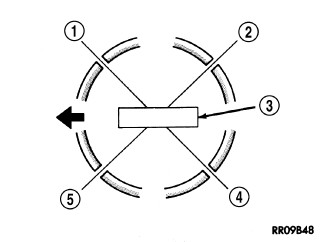
Position the piston ring end gaps as follows:
- Oil ring expander gap (5)
- Oil ring lower side rail end gap (4)
- Oil ring upper side rail end gap (1)
- No. 2 (intermediate) ring end gap (5)
-
No. 1 (upper) ring end gap (2)
NOTE: Typical V6 engine configuration shown.
NOTE: Ensure the position of the ring end gaps does not change when installing the ring compressor.
-
Lubricate the piston rings with clean engine oil. Position Piston Compressor C-385 (2) over the piston and rings. Tighten the compressor (2).
NOTE: Install the rod bearings in pairs. Do not mix sizes or use a new bearing half with an old bearing half.
- Install the bearing shell (8) on the connecting rod with the tang inserted into the machined groove in the rod. Lubricate the bearing surface with clean engine oil.
-
Remove the plastic guide plates (3) from the Guide Pins 8189 (7) and install the Guide Pins to the connecting rod being installed.
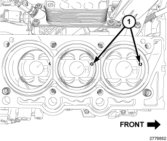
NOTE: Right cylinder bank shown, left cylinder bank similar.
- The pistons crowns are stamped with a mark (1) indicating installation position. This mark must be positioned toward the front of engine on both cylinder banks.
- Wipe the cylinder bore clean and lubricate with clean engine oil.
-
Rotate the crankshaft until the connecting rod journal is on the center of cylinder bore.
CAUTION: Avoid contact with the piston oil cooler jet(s). Positioning of the oil cooler jet(s) is critical for proper engine operation.
- Insert the piston and connecting rod into the cylinder bore and carefully position the guide pins over the crankshaft journal.
-
Tap the piston down in the cylinder bore using a hammer handle while guiding the connecting rod into position over the rod journal.
NOTE: Typical V6 engine configuration shown.
CAUTION: The connecting rod bolts must not be reused. Always replace the connecting rod bolts whenever they are loosened or removed.
-
Install the bearing shell (6) on the connecting rod cap (4) with the tang inserted into the machined groove in the cap. Lubricate the bearing surface with clean engine oil.
NOTE: Do not lubricate the threads of the connecting rod cap bolts (5).
- Install the connecting rod cap and bearing with the tang on the same side as the rod. Tighten the the NEW connecting rod cap bolts (5) to 20 N·m (15 ft. lbs.) plus 90°.
- If required, check the connecting rod side clearance (Refer to 09 - Engine/Engine Block/ROD, Piston and Connecting - Standard Procedure)
-
Repeat the previous steps for each piston being installed.
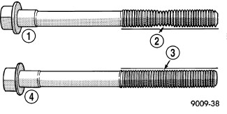
CAUTION: The main bearing cap bolts are tightened using a torque plus angle procedure. The bolts must be examined BEFORE reuse. If the threads are necked down the bolts must be replaced.
-
Check the main bearing cap bolts for necking by holding a scale or straight edge against the threads. If all the threads do not contact the scale (2) the bolt must be replaced.
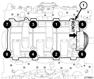
- Install the windage tray with eight main bearing cap bolts. Tighten the bolts in the sequence shown to 21 N·m (16 ft. lbs.) plus 90°.
- Install the engine oil pump and oil pump pick-up (Refer to 09 - Engine/Lubrication/PUMP, Engine Oil - Installation)
- Install the cylinder heads, engine timing cover and oil pans (Refer to 09 - Engine/Cylinder Head - Installation)
- If removed, install the oil filter and fill the engine crankcase with the proper oil to the correct level (Refer to 09 - Engine/Lubrication/OIL - Standard Procedure)
- Connect the negative battery cable and tighten nut to 5 N·m (45 in. lbs.).
- Fill the cooling system (Refer to 07 - Cooling - Standard Procedure) .
-
Operate the engine until it reaches normal operating temperature. Check cooling system for correct fluid level (Refer to 07 - Cooling - Standard Procedure)