STABILIZER BAR, Front
- STABILIZER BAR
- DISCONNECTING STABILIZER BAR
- STABILIZER BAR
- DISCONNECTING STABILIZER BAR
- STABILIZER BAR
- DISCONNECTING STABILIZER BAR
- SWITCH
- STABILIZER BAR
- DISCONNECTING STABILIZER BAR
- SWITCH
STABILIZER BAR
The stabilizer bar is on the bottom of the frame rails. Links are connected from the bar to the axle brackets. The stabilizer bar and links are isolated by rubber bushings.
DISCONNECTING STABILIZER BAR
This feature will provide feedback to the driver and be controlled by an electronic module (part of the stabilizer bar) which communicates via CAN C at 500 kbps. The disconnecting stabilizer bar module will read the ignition switch, vehicle speed, transfer case, and stabilizer bar switch messages on the CAN C bus and control the disconnecting stabilizer bar. The module will send a stabilizer bar status message and a lighting message on CAN C.
SWAY BAR SWITCH
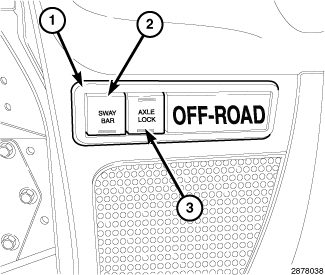 |
The OFF ROAD switch pod (1) is located on the instrument panel near the steering column. The switch pod contains a SWAY BAR switch (2) and a AXLE LOCK switch (3).
The switch pod housing and the push buttons are constructed of molded plastic. Each push button is clearly identified with the appropriate text. The SWAY BAR switch (2) is a momentary switch while the AXLE LOCK switch (2) is a rocker type switch.
Panel lamps dimmer controlled illumination lamps integral to the circuit board within the switch provide back lighting for visibility at night, but these lamps are not serviceable. The individual switches in the OFF ROAD switch pod cannot be repaired and are not serviced separately. If any component within the switch pod is ineffective or damaged, the entire switch pod unit must be replaced.
STABILIZER BAR
The stabilizer bar is used to control vehicle body roll during turns. The bar helps to control the vehicle body in relationship to the suspension.
DISCONNECTING STABILIZER BAR
STABILIZER BAR FAILSAFE
Stabilizer bar will ENGAGE with the loss of ignition switch, vehicle speed, or stabilizer bar switch signals
DISENGAGE
The bar will DISENGAGE when ALL the following conditions are met:
- vehicle speed under 18 MPH
- automatically at speeds over 14 MPH if the switch is in the ON position
- transfer case in 4 HI or 4 LO
- stabilizer bar switch message received for DISENGAGE
- ignition switch in the RUN or START position
- no stabilizer bar faults detected
ENGAGE
The bar will ENGAGE when ANY of the following conditions are met:
- vehicle speed is greater or equal to 18 MPH
- stabilizer bar switch message received for ENGAGE
- transfer case in 2WD or neutral
SWAY BAR SWITCH
The disconnecting stabilizer bar system will latch the momentary switch through software for an ignition switch OFF condition if the stabilizer bar was DISENGAGED and the transfer case was in 4LO at ignition switch OFF. Upon ignition switch RUN/START and the transfer case in 4LO, the system checks to verify all conditions to DISENGAGE the stabilizer bar are correct and then DISENGAGE the stabilizer bar without switch input.
STABILIZER BAR
 |
- Raise and support the vehicle.
-
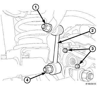
Remove the left upper stabilizer bar link nut (1) from the stabilizer bar.
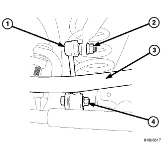
- Remove the right upper stabilizer bar link nut (2) from the stabilizer bar.
-
Remove the splash shield.
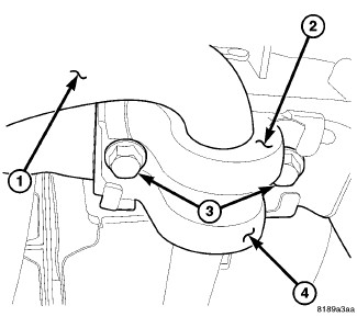
- Remove the right side stabilizer bar bracket bolts (3) to the frame.
- Remove the left side stabilizer bar bracket bolts (3) to the frame.
-
Remove the stabilizer bar (1) to the bench.
DISCONNECTING STABILIZER BAR
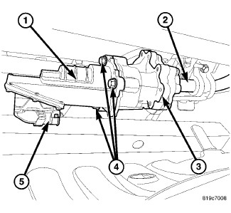 |
The disconnecting stabilizer bar unit (3) is not serviced separately from the bar (2). Do not disassemble this unit from the stabilizer bar.
WARNING:
| NOTE: |
The stabilizer links, stabilizer bar retainers/ bushings, stabilizer bar actuator (1) and the stabilizer bar (2) are serviceable. The new bar consists of the disconnecting unit (3) attached as an assembly to the bar (2).
|
|
- Raise and support the vehicle.
-
Hold the stabilizer link (1) shafts with a wrench and remove the link nuts (2) at the stabilizer bar.
NOTE: Before removing the connector (5) from the actuator clean the outside of the connector with a cleaner and compressed air, to remove any dirt or debris.
- Disconnect the electronic actuator electrical connector (5) for the disconnecting stabilizer bar.
-
Remove the actuator bolts (4) then remove the actuator (1) If replacing the stabilizer bar
(Refer to 02 - Front Suspension/Front/ACTUATOR, Stabilizer Bar - Removal)
.
-
Remove the stabilizer bar retainers (4) from the frame rails and remove the stabilizer bar (1).
SWITCH
 |
- Disconnect and isolate the negative battery cable.
-
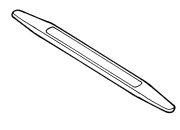
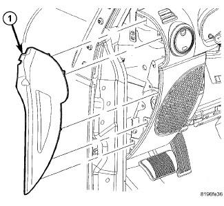
Using trim stick C-4755 or equivalent, remove the end cap (1).
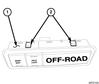
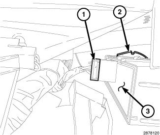
NOTE: The off road switch pod (1) has 2 upper tabs (2), and 2 lower tabs (directly below the upper tabs on the pod, not shown) that must be pushed toward the switch pod to release the pod from the instrument panel.
-
Disconnect the electrical connector (1).
NOTE: Using trim stick C-4755 or equivalent, pry out on the upper edge of the switch pod on the instrument panel face for tension while releasing the retaining tabs.
- Using trim stick C-4755 or equivalent, push the outside upper pod retaining tab (2) down to release, then the same for the inside upper retaining tab (not shown).
-
Release the lower retaining tabs (not shown) in the same manner as the upper retaining tabs (2) while rotating slightly down and away from the instrument panel.
STABILIZER BAR
|
-
Install the stabilizer bar (1) to the vehicle.
NOTE: Stabilizer bar link to axle bolt should be tightened with vehicle sitting on its tires
- Install the right side stabilizer bar bracket bolts (3) to the frame. Tighten to 102 N·m (75 ft. lbs.).
- Install the left side stabilizer bar bracket bolts (3) to the frame. Tighten to 102 N·m (75 ft. lbs.).
-
Install the splash shield.
-
Install the right upper stabilizer bar link nut (2) to the stabilizer bar. Tighten to 102 N·m (75 ft. lbs.).
- Install the left upper stabilizer bar link nut (1) to the stabilizer bar. Tighten to 102 N·m (75 ft. lbs.).
-
Remove the support and lower the vehicle.
DISCONNECTING STABILIZER BAR
|
The disconnecting stabilizer bar unit (3) is not serviced separately from the bar (2). Do not disassemble this unit from the stabilizer bar.
WARNING:
| NOTE: |
The stabilizer links, stabilizer bar retainers/ bushings, stabilizer bar actuator (1) and the stabilizer bar (2) are serviceable. The new bar consists of the disconnecting unit (3) attached as an assembly to the bar.
|
|
- Position the stabilizer bar (1) on the frame rail and install the retainers (4) with bushings (2) and bolts (3). Ensure the bar is centered with equal spacing on both sides.
-
Tighten the retainer bolts (3) to 61 N·m (45 ft. lbs.).
NOTE: The seal must be clean and intact in the electrical connector (5) when reconnecting to the actuator (1).
- Install the actuator (1) to the disconnecting unit (3) If the actuator was removed (Refer to 02 - Front Suspension/Front/ACTUATOR, Stabilizer Bar - Installation) .
-
Reconnect the electronic actuator electrical connector (5) for the disconnecting stabilizer bar (2).
NOTE: Stabilizer bar link to axle bolt should be tightened with vehicle sitting on its tires
- Install links (1) and nuts (2) to the stabilizer bar. Hold the link shaft with a wrench and tighten the nuts (2) to 102 N·m (75 ft. lbs.).
- Remove the supports and lower the vehicle.
-
Using a scan tool program the new stabilizer bar to the vehicle.
SWITCH
|