BOOSTER, Power Brake
DESCRIPTION
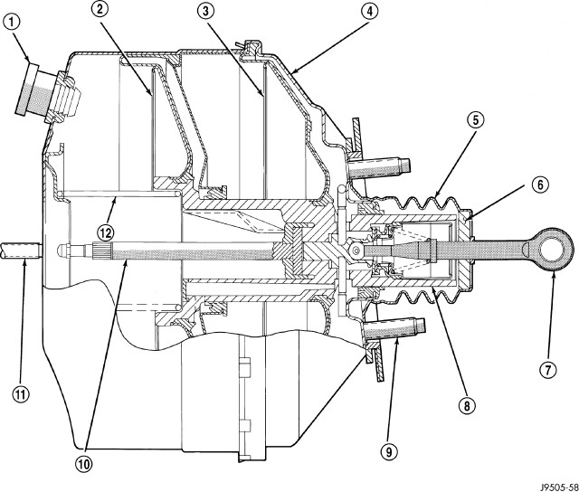
The booster assembly consists of a housing divided into separate chambers by two internal diaphragms. The outer edge of each diaphragm is attached to the booster housing.
Two push rods are used in the booster. The primary push rod connects the booster to the brake pedal. The secondary push rod connects the booster to the master cylinder to stroke the cylinder pistons.
OPERATION
The atmospheric inlet valve is opened and closed by the primary push rod. Booster vacuum supply is through a hose attached to an intake manifold fitting at one end and to the booster check valve at the other. The vacuum check valve in the booster housing is a one-way device that prevents vacuum leak back.
Power assist is generated by utilizing the pressure differential between normal atmospheric pressure and a vacuum. The vacuum needed for booster operation is taken directly from the engine intake manifold. The entry point for atmospheric pressure is through a filter and inlet valve at the rear of the housing .
The chamber areas forward of the booster diaphragms are exposed to vacuum from the intake manifold. The chamber areas to the rear of the diaphragms, are exposed to normal atmospheric pressure of 101.3 kilopascals (14.7 pounds/square in.).
Brake pedal application causes the primary push rod to open the atmospheric inlet valve. This exposes the area behind the diaphragms to atmospheric pressure. The resulting pressure differential provides the extra apply force for power assist.
The booster check valve, check valve grommet and booster seals are serviceable.
 |
DIAGNOSIS AND TESTING - MASTER CYLINDER/POWER BOOSTER
- Start the engine and check the booster vacuum hose connections. A hissing noise indicates a vacuum leak. Correct any vacuum leaks before proceeding.
- Stop the engine and pump the brake pedal until all vacuum reserve in the booster is depleted.
- Press and hold the brake pedal under light foot pressure. The pedal should hold firm. If the pedal falls away, there may be an external leak or the master cylinder is faulty (internal leakage).
- Start the engine and note pedal action. It should fall away slightly under light foot pressure, then hold firm. If no pedal action is discernible, the power booster, vacuum supply or vacuum check valve is faulty, proceed to the POWER BOOSTER VACUUM TEST.
- If the POWER BOOSTER VACUUM TEST passes, rebuild the booster vacuum reserve as follows: Release the brake pedal. Increase engine speed to 1500 RPM, close the throttle and immediately turn off the ignition to stop the engine.
- Wait a minimum of 90 seconds and try brake action again. The booster should provide two or more vacuum assisted pedal applications. If the vacuum assist is not provided, the booster is faulty.
POWER BOOSTER VACUUM TEST
- Connect a vacuum gauge to the booster check valve with a short length of hose and T-fitting.
- Start and run the engine at curb idle for one minute.
- Observe the vacuum supply. If the vacuum supply is less that 12 inches HG (406 millibars), repair the vacuum supply.
- Clamp the hose shut between the intake vacuum source and the check valve.
- Stop the engine and observe the vacuum gauge.
- If the vacuum drops more than one inch HG (33 millibars) within 15 seconds, the booster diaphragm or check valve is faulty.
POWER BOOSTER CHECK VALVE TEST
- Remove the power booster check valve from the power booster.
- Using a hand operated vacuum pump, apply 15-20 inches HG (508-677 millibars) vacuum at the booster side of the check valve.
- The vacuum should hold steady. If the gauge on the pump indicates vacuum loss, the check valve is faulty and should be replaced.
REMOVAL
| NOTE: |
LHD shown in graphics. The removal and installation procedures and torques specs are the same for the RHD. |
- Remove the master cylinder.
- Disconnect vacuum hose from booster check valve.
-
Remove retaining clip that secures booster push rod to brake pedal and slide the rod off the pin.
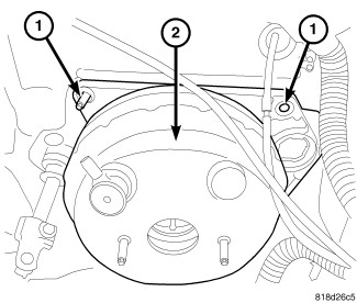
- Remove the nuts (1) attaching booster mounting plate to the front cowl panel.
-
In engine compartment, slide booster and mounting plate out of the cowl panel, and remove the booster assembly from engine compartment.
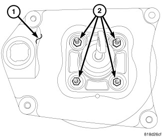
- Remove booster mounting nuts (2) from the mounting plate (1).
- Disconnect the clutch pedal from the clutch M/C if equipped.
-
Remove the booster from the mounting plate (1).
INSTALLATION
| NOTE: |
LHD shown in graphics. The removal and installation procedures and torques specs are the same for the RHD. |
|
- Clean the booster mounting surface.
- Install the booster on the mounting plate (1).
-
Install the booster mounting nuts (2) that attach booster to mounting plate. Tighten booster mounting nuts to 25 N·m (18 ft. lbs.).
- Install the booster assembly (2) with the mounting plate to the front cowl.
-
Install the booster mounting plate nuts (1) that attach the mounting plate to the front cowl. Tighten booster mounting plate nuts in an X pattern to 18 N·m (159 in. lbs.).
- Connect vacuum hose to booster check valve.
- Install master cylinder.
- Lubricate the pedal pin and bushing with Mopar multi-mileage grease. Then slide the booster push rod onto brake pedal pin and secure with retaining clip.
- Reconnect the clutch M/C to pedal if equipped.
- Top off master cylinder fluid level and bleed base brakes.