MASTER CYLINDER, Brake
- DESCRIPTION
- OPERATION
- DIAGNOSIS AND TESTING - MASTER CYLINDER/POWER BOOSTER
- STANDARD PROCEDURE - MASTER CYLINDER BLEEDING
- REMOVAL
- INSTALLATION
DESCRIPTION
The master cylinder has a removable plastic reservoir. The cylinder body is made of aluminum and contains a primary and secondary piston assembly. The cylinder body including the piston assemblies are not serviceable. If diagnosis indicates an internal problem with the cylinder body, it must be replaced as an assembly. The reservoir and grommets are the only replaceable parts on the master cylinder.
OPERATION
The master cylinder bore contains a primary and secondary piston. The primary piston supplies hydraulic pressure to the front brakes. The secondary piston supplies hydraulic pressure to the rear brakes. The master cylinder reservoir stores reserve brake fluid for the hydraulic brake circuits.
DIAGNOSIS AND TESTING - MASTER CYLINDER/POWER BOOSTER
- Start the engine and check the booster vacuum hose connections. A hissing noise indicates a vacuum leak. Correct any vacuum leaks before proceeding.
- Stop the engine and pump the brake pedal until all vacuum reserve in the booster is depleted.
- Press and hold the brake pedal under light foot pressure. The pedal should hold firm. If the pedal falls away, there may be an external leak or the master cylinder is faulty (internal leakage).
- Start the engine and note pedal action. It should fall away slightly under light foot pressure, then hold firm. If no pedal action is discernible, the power booster, vacuum supply or vacuum check valve is faulty, proceed to the POWER BOOSTER VACUUM TEST.
- If the POWER BOOSTER VACUUM TEST passes, rebuild the booster vacuum reserve as follows: Release the brake pedal. Increase engine speed to 1500 RPM, close the throttle and immediately turn off the ignition to stop the engine.
- Wait a minimum of 90 seconds and try brake action again. The booster should provide two or more vacuum assisted pedal applications. If the vacuum assist is not provided, the booster is faulty.
POWER BOOSTER VACUUM TEST
- Connect a vacuum gauge to the booster check valve with a short length of hose and T-fitting.
- Start and run the engine at curb idle for one minute.
- Observe the vacuum supply. If the vacuum supply is less that 12 inches HG (406 millibars), repair the vacuum supply.
- Clamp the hose shut between the intake vacuum source and the check valve.
- Stop the engine and observe the vacuum gauge.
- If the vacuum drops more than one inch HG (33 millibars) within 15 seconds, the booster diaphragm or check valve is faulty.
POWER BOOSTER CHECK VALVE TEST
- Remove the power booster check valve from the power booster.
- Using a hand operated vacuum pump, apply 15-20 inches HG (508-677 millibars) vacuum at the booster side of the check valve.
- The vacuum should hold steady. If the gauge on the pump indicates vacuum loss, the check valve is faulty and should be replaced.
STANDARD PROCEDURE - MASTER CYLINDER BLEEDING
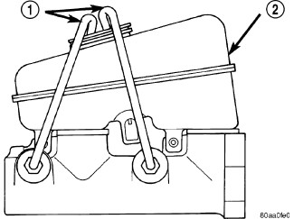
A new master cylinder should be bled before installation on the vehicle. Required bleeding tools include bleed tubes and a wood dowel to stroke the pistons. Bleed tubes can be fabricated from brake line.
- Mount master cylinder in vise.
- Attach bleed tubes to cylinder outlet ports. Then position each tube end into reservoir.
- Fill reservoir with fresh brake fluid.
- Press cylinder pistons inward with wood dowel. Then release pistons and allow them to return under spring pressure. Continue bleeding operations until air bubbles are no longer visible in fluid.
 |
REMOVAL
| NOTE: |
LHD shown in graphics. The removal and installation procedures and torques specs are the same for the RHD. |
 |
The vacuum in the power brake
booster must be depleted before removing the master cylinder to avoid
damaging the master cylinder and to prevent inhalation of the o-ring
or any other contamination into the booster. The preferred method
is to pump the brake pedal while the engine is not running until the
brake pedal becomes firm. An alternative method is to remove and immediately
reinstall the check valve located on the booster. If the check valve
is removed, special care should be taken to ensure that the grommet
is not damaged and remains seated, the check valve is dry and free
of debris, and that contaminates cannot be ingested during removal.
CAUTION:
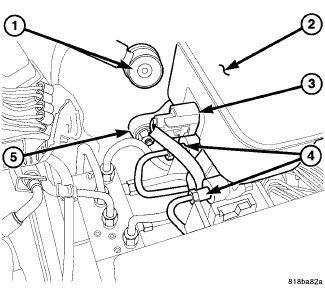
- With the engine off, depress the brake pedal five times to deplete any vacuum that may remain in the booster unit.
- Siphon and drain the fluid from the reservoir (2).
- Disconnect the fluid level electrical connector (3) from the reservoir (2).
- Remove the brake lines (4) at the master cylinder.
-
Remove mounting nuts (5) from the master cylinder.
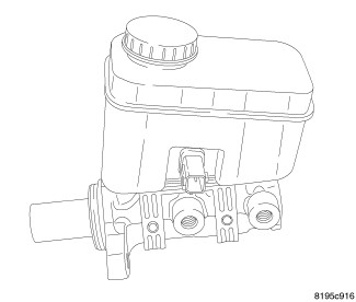
- Remove master cylinder.
- Remove cylinder cover and drain the rest of the fluid.
-
If master cylinder reservoir requires service, (Refer to 05 - Brakes/Hydraulic/Mechanical/RESERVOIR, Brake Master Cylinder - Removal)
.
INSTALLATION
| NOTE: |
LHD shown in graphics. The removal and installation procedures and torques specs are the same for the RHD. |
|
| NOTE: |
If master cylinder
is replaced, bleed cylinder before installation. |
 |
-
Clean cylinder mounting
surface of brake booster (3).
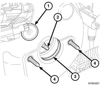
NOTE: Insure the O-ring is on the master cylinder at the booster interface.
-
Install master cylinder
onto brake booster studs (4).
- Install NEW mounting nuts (5) and tighten to 17 N·m (151 in. lbs.).
- Connect the brake lines (4) to the master cylinder and tighten to 19 N·m (168 in. lbs.).
- Connect fluid level electrical connector (3) to the reservoir (2).
-
Fill and bleed base
brake system, (Refer to 05 -
Brakes - Standard Procedure)
.