CONSOLE, Center
REMOVAL
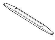
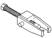
Special Tools: Click to display a list of tools used in this procedure
 |
- Remove the 12V power outlet. (Refer to 08 - Electrical/8W - Wiring/Power Distribution/OUTLET, Power - Removal)
- Remove the 115V power outlet. (Refer to 08 - Electrical/8W - Wiring/Power Distribution/OUTLET, Power - Removal)
-
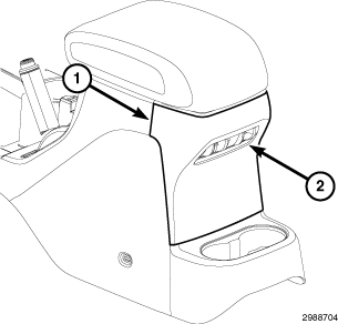
Using a trim stick C-4755 or equivalent, remove the rear console bezel (1) and disconnect
the electrical connectors (2), if equipped.
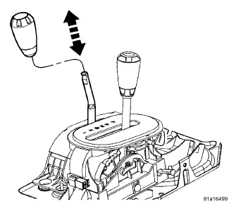
NOTE: Most transfer case shift knobs can be remove by hand. The motion should mimic that of a slide hammer. Constant force doesn't aid in the removal of the knob.
-
Slide the transfer
case shift lever back towards the seat and pull in an upward motion
with a "quick" snap to remove the knob.
-
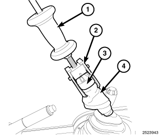
If removal of the transfer
case shift knob by hand is not possible wrap a shop towel or equivalent
(4) around the base of the shift knob (3) and using puller C-4333A-1 or equivalent (2) and slide hammer (1), remove the shift knob
from the shift lever.
-
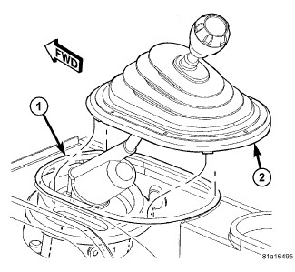
On manual transmission
vehicles, using a trim stick C-4755 or equivalent, separate the shifter boot (2) from the console
bezel (1).
- Remove the cup holder or ash receiver, if equipped.
-
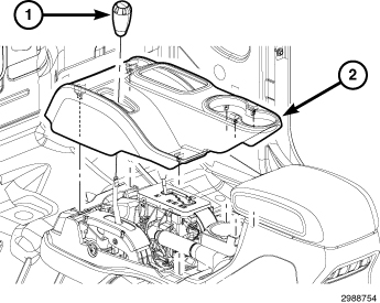
Using a trim stick C-4755 or equivalent, separate the retaining clips and remove the
console bezel (2).
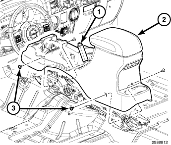
- Position the brake lever (1) into the full up position.
- Remove the four screws (3) and separate the console (2).
- Disconnect the electrical connectors and separate the harness supports from the console.
-
Remove the console.
INSTALLATION
|
- Position the console (2) over the shifters and brake levers and seat fully.
-
Install the four screws
(3).
- Position the bezel (2) over the shifters seat the clips fully.
- Install the cup holder and ash receiver, if equipped.
-
If equipped, position
the transfer case shifter knob (1) onto the shift shaft, a audible
click should be heard when the shifter knob is fully seated.
- Seat the shifter boot (2) onto the console bezel (1) and seat fully.
-
Connect battery negative
cable.
- Connect the electrical connectors (2), if equipped.
- Position the rear bezel (1) back into place and seat the clips fully.
- Install the 115V power outlet. (Refer to 08 - Electrical/8W - Wiring/Power Distribution/OUTLET, Power - Installation)
-
Install the 12V power
outlet. (Refer to 08 - Electrical/8W
- Wiring/Power Distribution/OUTLET, Power - Installation)