COOLER, Oil
DESCRIPTION
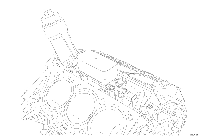 |
The oil cooler is attached to the top of the oil filter housing which is located in the V of the cylinder block. The oil cooler is a plate style coolant-to-oil heat exchanger.
OPERATION
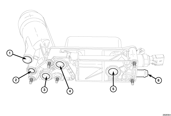 |
Oil flows from the engine oil pump to the oil filter housing inlet (1) and to the oil filter element located within the oil filter housing. After the oil is filtered it travels internally through the engine oil cooler and then to the main oil gallery (5).
Coolant flows from the right cylinder block water jacket (3) and from the left cylinder block water jacket (4) into the housing. The coolant flows through the oil cooler and exits the housing from the rear hose nipple (6) where it is returned to the water pump. A coolant by-pass in the housing is designed to direct excessive coolant flow around the oil cooler for continuous circulation.
REMOVAL
 |
| NOTE: |
The oil cooler can not be cleaned out. In the event that the engine requires rebuilding or replacement, replace the oil cooler. |
- Perform the fuel pressure release procedure (Refer to 14 - Fuel System/Fuel Delivery - Standard Procedure) .
- Disconnect and isolate the negative battery cable.
- Drain the cooling system (Refer to 07 - Cooling - Standard Procedure) .
- Remove the air cleaner housing assembly, upper and lower intake manifolds (Refer to 09 - Engine/Manifolds/MANIFOLD, Intake - Removal)
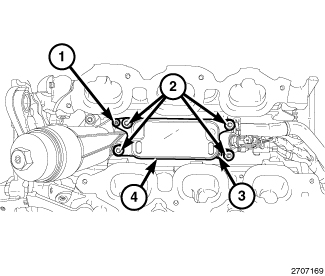
- Remove four bolts (2) and two screws (1) and (3).
-
Remove the oil cooler (4).
-
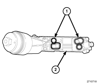
Remove and discard the oil cooler seals (1).
INSTALLATION
|
| NOTE: |
Always use new dry seals (1) when installing the oil cooler. Do not lubricate the seals. |
-
Install the new oil cooler seals (1) onto the oil filter housing (2).
- Position the oil cooler (4) on the oil filter housing.
- Install two screws (1) and (3). Tighten the screws to 4 N·m (35 in. lbs.).
- Install four bolts (2) and tighten to 12 N·m (106 in. lbs.).
- Install the upper and lower intake manifolds and air cleaner housing assembly (Refer to 09 - Engine/Manifolds/MANIFOLD, Intake - Installation)
- Fill the engine crankcase with the proper oil to the correct level (Refer to 09 - Engine/Lubrication/OIL - Standard Procedure)
- Connect the negative battery cable and tighten nut to 5 N·m (45 in. lbs.).
- Fill the cooling system (Refer to 07 - Cooling - Standard Procedure) .
-
Operate the engine until it reaches normal operating temperature. Check cooling system for correct fluid level (Refer to 07 - Cooling - Standard Procedure)