CHAIN and SPROCKETS, Timing
REMOVAL
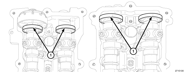 |
The magnetic timing wheels (1)
must not come in contact with magnets (pickup tools, trays, etc.)
or any other strong magnetic field. This will destroy the timing wheels
ability to correctly relay camshaft position to the camshaft position
sensor.
CAUTION:
When the timing chains are removed
and the cylinder heads are still installed, DO NOT rotate the camshafts
or crankshaft without first locating the proper crankshaft position.
Failure to do so will result in valve and/or piston damage.
CAUTION:
| NOTE: |
The Variable Valve Timing (VVT) assemblies (Phasers) and Oil Control Valves (OCVs) can be serviced without removing the engine timing cover (Refer to 09 - Engine/Cylinder Head/ASSEMBLY, Variable Valve Timing - Removal) . |
- Disconnect and isolate the negative battery cable.
- Remove the air cleaner housing assembly and upper intake manifold (Refer to 09 - Engine/Manifolds/MANIFOLD, Intake - Removal)
- Remove both cylinder head covers (Refer to 09 - Engine/Cylinder Head/COVER(S) , Cylinder Head - Removal)
- Remove the spark plugs (Refer to 08 - Electrical/8I - Ignition Control/SPARK PLUG - Removal) .
- Raise and support the vehicle (Refer to 04 - Vehicle Quick Reference/Hoisting - Standard Procedure) .
- Drain the cooling system (Refer to 07 - Cooling - Standard Procedure) .
-
Remove the oil pan,
accessory drive belts, crankshaft vibration damper and engine timing
cover (Refer to 09 - Engine/Valve
Timing/COVER(S)
, Engine Timing - Removal)
NOTE: Take this opportunity to measure timing chain wear (Refer to 09 - Engine/Valve Timing - Standard Procedure) .
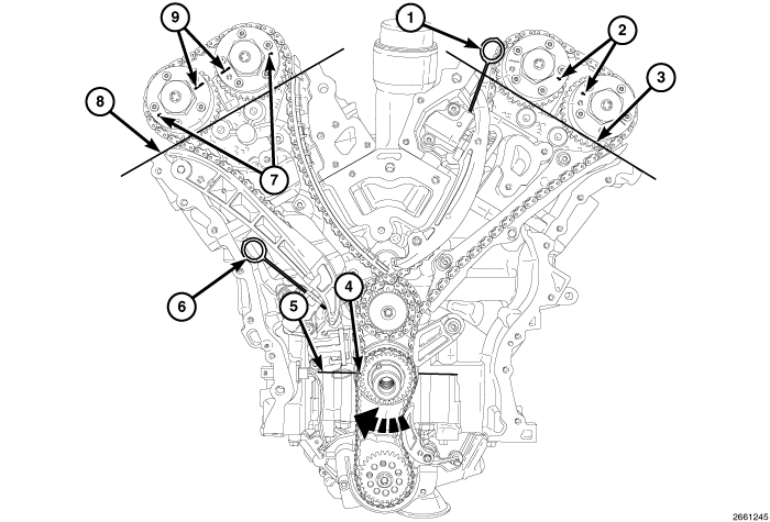
CAUTION: When aligning timing marks, always rotate engine by turning the crankshaft. Failure to do so will result in valve and/or piston damage.
- Rotate the crankshaft clockwise (as viewed from the front) to place the number one cylinder piston at top-dead-center on the exhaust stroke by aligning the dimple (4) on the crankshaft with the block/bearing cap junction (5).
-
While maintaining this
alignment, verify that the ARROWS (2) on the
left side cam phasers point toward each other and are parallel to
the cylinder head cover mounting surface (3) and that the right side
cam phaser ARROWS (7) point away from each other and the SCRIBE LINES (9)
are parallel to the cylinder head cover mounting surface (8).
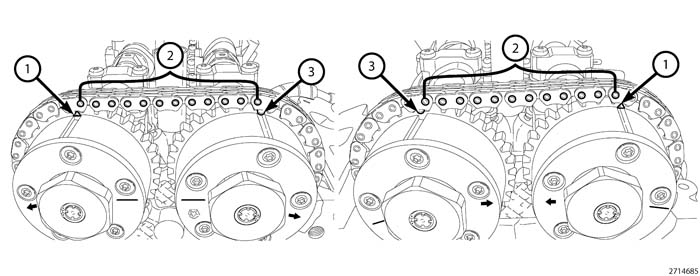
NOTE: The phaser markings (1 and 3) could align with either an external or internal chain link. Either alignment is acceptable as long as there are twelve chain pins between the markings.
-
There should be twelve
chain pins (2) BETWEEN the exhaust cam phaser triangle marking (1) and the intake cam phaser
circle marking (3) as viewed from either the front or rear of the
cam phasers.
CAUTION: Always reinstall timing chains so that they maintain the same direction of rotation. Inverting a previously run chain on a previously run sprocket will result in excessive wear to both the chain and sprocket.
-
Mark the direction
of rotation on the following timing chains using a paint pen or equivalent
to aid in reassembly:
-
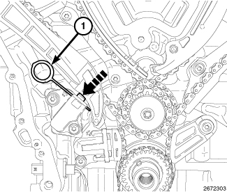
Reset the right side
cam chain tensioner by pushing back the tensioner piston and installing
Tensioner Pin 8514 (1).
-
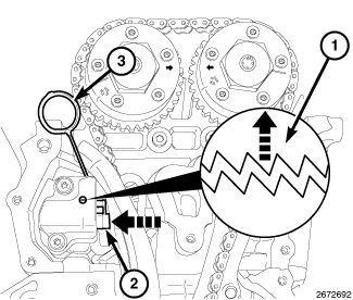
Reset the left side
cam chain tensioner by lifting the pawl (1), pushing back the piston
(2) and installing Tensioner Pin 8514 (3) (Refer to 09 - Engine/Valve
Timing - Standard Procedure)
.
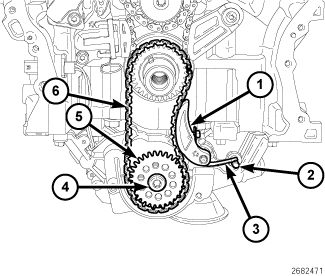
- Disengage the oil pump chain tensioner spring (3) from the dowel pin (2) and remove the oil pump chain tensioner (1).
-
Remove the oil pump
sprocket T45 retaining bolt (4) and remove the oil pump sprocket (5)
and oil pump chain (6).
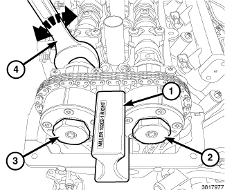
NOTE: It may be necessary to rock the camshaft slightly (a few degrees) with a wrench (4) when installing the camshaft phaser lock.
- Install the Lock, Camshaft/Phaser, Right Side 10202-1 (1) with the tool number facing up.
- Loosen, but do not remove, the exhaust oil control valve (3) and the intake oil control valve (2).
- Remove the Lock, Camshaft/Phaser, Right Side 10202-1 (1).
- Remove the oil control valve (2) from the right side intake cam phaser.
- Pull the right side intake cam phaser off of the camshaft and remove the right side cam chain.
-
If required, remove
the oil control valve (3) and pull the right side exhaust cam phaser
off of the camshaft.
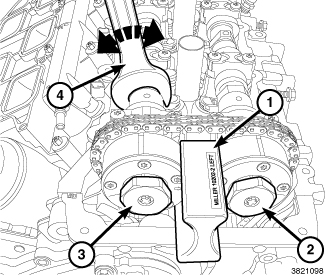
NOTE: It may be necessary to rock the camshaft slightly (a few degrees) with a wrench (4) when installing the camshaft phaser lock.
- Install the Lock, Camshaft/Phaser, Left Side 10202-2 (1) with the tool number facing up.
- Loosen, but do not remove, the exhaust oil control valve (2) and the intake oil control valve (3).
- Remove the Lock, Camshaft/Phaser, Left Side 10202-2 (1).
- Remove the oil control valve (2) from the left side exhaust cam phaser.
- Pull the left side exhaust cam phaser off of the camshaft and remove the left side cam chain.
-
If required, remove
the oil control valve (3) and pull the left side intake cam phaser
off of the camshaft.
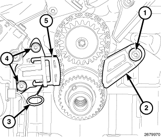
- Reset the primary chain tensioner (5) by pushing back the tensioner piston and installing Tensioner Pin 8514 (3). Remove two T30 bolts (4) and remove the primary chain tensioner.
-
Remove the T30 bolt
(1) and the primary chain guide (2).
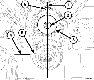
- Remove the idler sprocket T45 retaining bolt (2) and washer (3).
-
Remove the primary
chain, idler sprocket and crankshaft sprocket as an assembly.
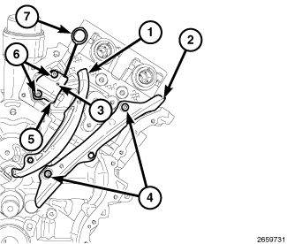
- If required, remove two T30 bolts (6) and the left side cam chain tensioner (5).
-
If required, remove
two T30 bolts (4) and the left side cam chain guide (2) and tensioner
arm (1).
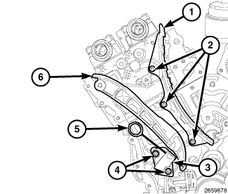
- If required, remove two T30 bolts (4) and the right side cam chain tensioner (3).
- If required, remove three T30 bolts (2) and the right side cam chain guide (1) and tensioner arm (6).
-
Inspect all sprockets
and chain guides. Replace if damaged.
INSPECTION
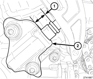 |
Prior to disassembly of the timing chains and sprockets, measure the timing chain wear (1) (Refer to 09 - Engine/Valve Timing - Standard Procedure)
.
Inspect the following valve timing components:
- Sprockets for excessive tooth wear. Some tooth markings are normal and not a cause for sprocket replacement.
- Idler sprocket assembly bushing and shaft for excessive wear.
- Chain guides and tensioner arms. Replace these parts if grooving in plastic face is more than 1 mm (0.039 in.) deep.
- Secondary chain tensioner piston and ratcheting device. Inspect for evidence of heavy contact between tensioner piston and tensioner arm. If this condition exist the tensioner arm and chain should be replaced.
- Primary chain tensioner plastic faces. Replace as required.
INSTALLATION
 |
|
The magnetic timing wheels (1)
must not come in contact with magnets (pickup tools, trays, etc.)
or any other strong magnetic field. This will destroy the timing wheels
ability to correctly relay camshaft position to the camshaft position
sensor.
CAUTION:
|
- Inspect all sprockets and chain guides. Replace if damaged.
- If removed, install the right side cam chain guide (1) and tensioner arm (6). Tighten attaching T30 bolts (2) to 12 N·m (106 in. lbs.).
- If removed, install the right side cam chain tensioner (3) to the engine block with two bolts (4). Tighten the T30 bolts (4) to 12 N·m (106 in. lbs.).
-
Reset the right side
cam chain tensioner (3) by pushing back the tensioner piston and installing
Tensioner Pin 8514 (5).
- If removed, install the left side cam chain guide (2) and tensioner arm (1). Tighten attaching T30 bolts (4) to 12 N·m (106 in. lbs.).
- If removed, install the left side cam chain tensioner (5) to the cylinder head with two bolts (6). Tighten the T30 bolts (6) to 12 N·m (106 in. lbs.).
-
Reset the left side
cam chain tensioner (5) by lifting the pawl (3), pushing back the
piston and installing Tensioner Pin 8514 (7) (Refer to 09 - Engine/Valve
Timing - Standard Procedure)
.
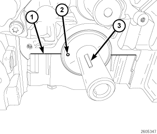
-
Verify that the key
(3) is installed in the crankshaft.
CAUTION: Do not rotate the crankshaft more than a few degrees independently of the camshafts. Piston to valve contact could occur resulting in possible valve damage. If the crankshaft needs to be rotated more than a few degrees, first remove the camshafts .
-
Verify that the number
one cylinder piston is positioned at top-dead-center by aligning the
dimple (2) on the crankshaft with the block/bearing cap junction (1).
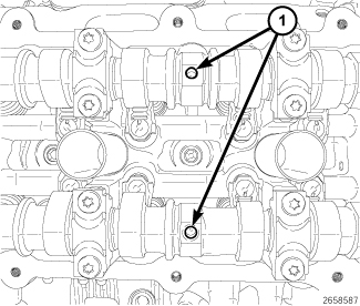
CAUTION: Do not rotate the camshafts more than a few degrees independently of the crankshaft. Valve to piston contact could occur resulting in possible valve damage. If the camshafts need to be rotated more than a few degrees, first move the pistons away from the cylinder heads by rotating the crankshaft counterclockwise to a position 30° before-top-dead-center. Once the camshafts are returned to their top-dead-center position, rotate the crankshaft clockwise to return the crankshaft to top-dead-center.
-
Verify that the camshafts
are set at top-dead-center by positioning the alignment holes (1)
vertically.
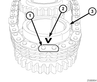
CAUTION: Always reinstall timing chains so that they maintain the same direction of rotation. Inverting a previously run chain on a previously run sprocket will result in excessive wear to both the chain and sprocket.
-
Place the primary chain
onto the crankshaft sprocket (3) so that the arrow (2) is aligned
with the plated link (1) on the timing chain.
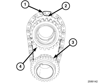
-
While maintaining this
alignment, invert the crankshaft sprocket and timing chain and place
the idler sprocket (4) into the timing chain so that the dimple (2)
is aligned with the plated link (1) on the timing chain.
- While maintaining this alignment, lubricate the idler sprocket bushing with clean engine oil and install the sprockets and timing chain on the engine. To verify that the timing is still correct, the timing chain plated link (6) should be located at 12:00 (1) when the dimple (5) on the crankshaft is aligned with the block/bearing cap junction (4).
-
Install the idler sprocket
retaining bolt (2) and washer (3). Tighten the T45 bolt (2) to 25
N·m (18 ft. lbs.).
- Install the primary chain guide (2). Tighten attaching T30 bolt (1) to 12 N·m (106 in. lbs.).
- Reset the primary chain tensioner (5) by pushing back the tensioner piston and installing Tensioner Pin 8514 (3).
-
Install the primary
chain tensioner (5) to the engine block with two bolts (4). Tighten
the T30 bolts (4) to 12 N·m (106 in. lbs.) and remove the Tensioner
Pin 8514 (3).
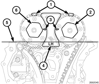
-
Press the left side
intake cam phaser onto the intake camshaft. Install and hand tighten
the oil control valve (6).
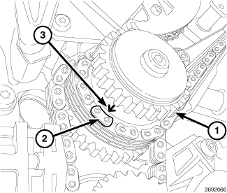
NOTE: The left side and right side cam chains are identical.
CAUTION: Always reinstall timing chains so that they maintain the same direction of rotation. Inverting a previously run chain on a previously run sprocket will result in excessive wear to both the chain and sprocket.
-
Drape the left side
cam chain over the left side intake cam phaser and onto the idler
sprocket (1) so that the arrow (3) is aligned with the plated link
(2) on the cam chain.
-
While maintaining this
alignment, route the cam chain around the exhaust and intake cam phasers
so that the plated links are aligned with the phaser timing marks
(1). Position the left side cam phasers so that the arrows (3) point
toward each other and are parallel to the cylinder head cover mounting
surface (5). Press the exhaust cam phaser onto the exhaust cam, install
and hand tighten the oil control valve (2).
NOTE: Minor rotation of a camshaft (a few degrees) may be required to install the camshaft phaser or phaser lock.
- Install the Lock, Camshaft/Phaser, Left Side 10202-2 (4) with the tool number facing up.
- Tighten the oil control valves (2) and (6) to 150 N·m (110 ft. lbs.).
-
Remove the Camshaft
Phaser Lock (4).
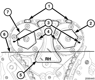
-
Press the right side
exhaust cam phaser onto the exhaust camshaft. Install and hand tighten
the oil control valve (7).
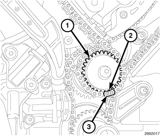
CAUTION: Always reinstall timing chains so that they maintain the same direction of rotation. Inverting a previously run chain on a previously run sprocket will result in excessive wear to both the chain and sprocket.
-
Drape the right side
cam chain over the right side exhaust cam phaser and onto the idler
sprocket (1) so that the dimple (2) is aligned with the plated link
(3) on the cam chain.
-
While maintaining this
alignment, route the cam chain around the exhaust and intake cam phasers
so that the plated links are aligned with the phaser timing marks
(1). Position the right side cam phasers so that the arrows (3) point
away from each other and the scribe lines (4) are parallel to the
cylinder head cover mounting surface (6). Press the intake cam phaser
onto the intake cam, install and hand tighten the oil control valve
(2).
NOTE: Minor rotation of a camshaft (a few degrees) may be required to install the camshaft phaser or phaser lock.
- Install the Lock, Camshaft/Phaser, Right Side 10202-1 (5) with the tool number facing up.
- Tighten the oil control valves (2) and (7) to 150 N·m (110 ft. lbs.).
-
Remove the Camshaft
Phaser Lock (5).
NOTE: There are no timing marks on the oil pump gear or chain.
CAUTION: Always reinstall timing chains so that they maintain the same direction of rotation. Inverting a previously run chain on a previously run sprocket will result in excessive wear to both the chain and sprocket.
- Place the oil pump sprocket (5) into the oil pump chain (6). Place the oil pump chain onto the crankshaft sprocket while aligning the oil pump sprocket with the oil pump shaft. Install the oil pump sprocket T45 retaining bolt (4) and tighten to 25 N·m (18 ft. lbs.).
-
Install the oil pump
chain tensioner (1). Make sure that the spring (3) is positioned above
the dowel pin (2).
- Remove the Tensioner Pins 8514 (1) and (6) from the right side and left side cam chain tensioners.
- Rotate the crankshaft clockwise (as viewed from the front) two complete revolutions stopping when the dimple (4) on the crankshaft is aligned with the block/bearing cap junction (5).
-
While maintaining this
alignment, verify that the ARROWS (2) on the
left side cam phasers point toward each other and are parallel to
the cylinder head cover mounting surface (3) and that the right side
cam phaser ARROWS (7) point away from each other and the SCRIBE LINES (9)
are parallel to the cylinder head cover mounting surface (8).
- There should be 12 chain pins (2) BETWEEN the exhaust cam phaser triangle marking (1) and the intake cam phaser circle marking (3) as viewed from either the front or rear of the cam phasers.
-
If the engine timing
is not correct, repeat this procedure.
- Install the engine timing cover, crankshaft vibration damper, accessory drive belts and oil pan (Refer to 09 - Engine/Valve Timing/COVER(S) , Engine Timing - Installation)
- Install the spark plugs. Tighten to 17.5 N·m (13 ft. lbs.) (Refer to 08 - Electrical/8I - Ignition Control/SPARK PLUG - Installation) .
- Install the cylinder head covers (Refer to 09 - Engine/Cylinder Head/COVER(S) , Cylinder Head - Installation)
- Install the upper intake manifold and air cleaner housing assembly (Refer to 09 - Engine/Manifolds/MANIFOLD, Intake - Installation)
- Fill the engine crankcase with the proper oil to the correct level (Refer to 09 - Engine/Lubrication/OIL - Standard Procedure)
- Connect the negative battery cable and tighten nut to 5 N·m (45 in. lbs.).
- Fill the cooling system (Refer to 07 - Cooling - Standard Procedure) .
- Operate the engine until it reaches normal operating temperature. Check cooling system for correct fluid level (Refer to 07 - Cooling - Standard Procedure)
| NOTE: |
The Cam/Crank Variation Relearn procedure must be performed using the scan tool anytime there has been a repair/replacement made to a powertrain system, for example: flywheel, valvetrain, camshaft and/or crankshaft sensors or components. |