Align the markings on the roof headlining assembly with the 2 No. 2 roof silencer pads and install the pads using hot-melt glue as shown in the illustration.
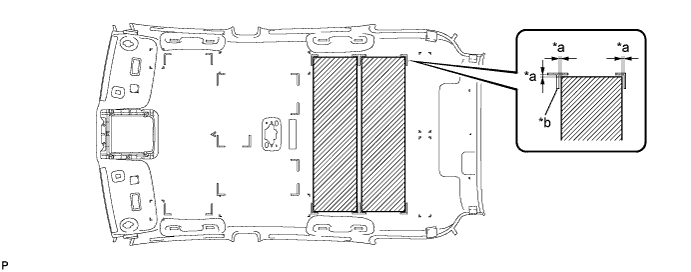
| *a | 5 mm (0.197 in.) | *b | Marking |
ROOF HEADLINING > REASSEMBLY |
| 1. INSTALL NO. 2 ROOF SILENCER PAD (w/o Sliding Roof) |
Align the markings on the roof headlining assembly with the 2 No. 2 roof silencer pads and install the pads using hot-melt glue as shown in the illustration.
| *a | 5 mm (0.197 in.) | *b | Marking |
| 2. INSTALL NO. 2 ROOF SILENCER PAD (w/ Sliding Roof) |
Align the markings on the roof headlining assembly with the No. 2 roof silencer pad and install the pad using hot-melt glue as shown in the illustration.
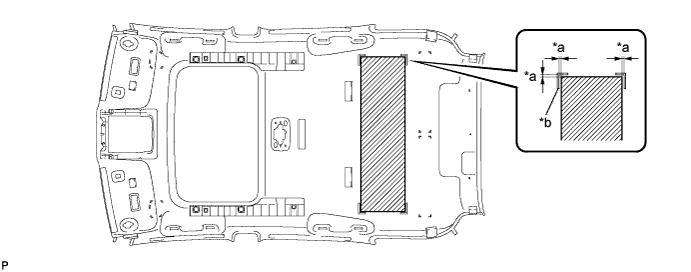
| *a | 5 mm (0.197 in.) | *b | Marking |
| 3. INSTALL NO. 4 ROOF SILENCER PAD (w/o Sliding Roof) |
Align the markings on the roof headlining assembly with the No. 4 roof silencer pad and install the pad using hot-melt glue as shown in the illustration.
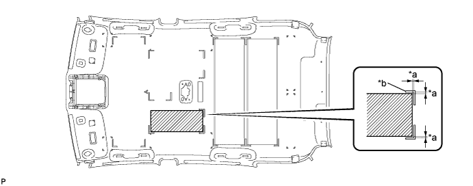
| *a | 5 mm (0.197 in.) | *b | Marking |
| 4. INSTALL NO. 3 ROOF SILENCER PAD (w/o Sliding Roof) |
Align the markings on the roof headlining assembly with the No. 3 roof silencer pad and install the pad using hot-melt glue as shown in the illustration.
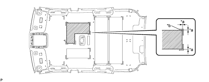
| *a | 5 mm (0.197 in.) | *b | Marking |
| 5. INSTALL NO. 1 ROOF SILENCER PAD (w/o Sliding Roof) |
Align the markings on the roof headlining assembly with the No. 1 roof silencer pad and install the pad using hot-melt glue as shown in the illustration.
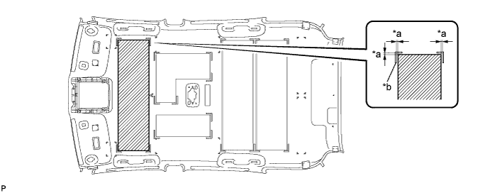
| *a | 5 mm (0.197 in.) | *b | Marking |
| 6. INSTALL NO. 1 ROOF WIRE |
Apply double-sided tape as shown in the illustration.
Peel off the release paper from the double-sided tape.
Attach the No. 1 roof wire along the double-sided tape so that the marking surface of the wire harness faces downward.
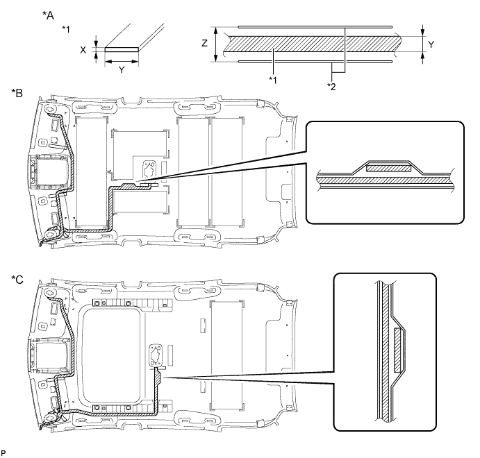
| *A | Tape Attachment Locations (Reference) | *B | w/o Sliding Roof |
| *C | w/ Sliding Roof | - | - |
| *1 | Double-sided Tape | - | - |
| *a | Marking | - | - |
Align the pink marking tape (A) on the front part of the No. 1 roof wire with the front tab of the roof headlining assembly.
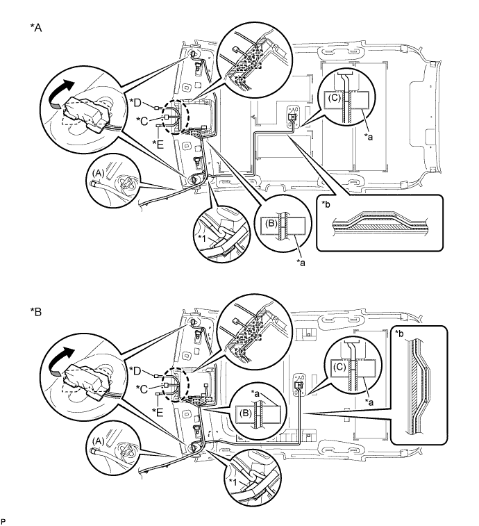
| *A | w/o Sliding Roof | *B | w/ Sliding Roof |
| *C | w/ EC Mirror | *D | w/ Rain Sensor (for LHD), w/ Humidity Sensor (for RHD) |
| *E | w/ Humidity Sensor (for LHD), w/ Rain Sensor (for RHD) | - | - |
| *1 | Joint Box | - | - |
| *a | Marking | *b | Adjustment Area |
Align the joint box with the roof headlining marking, and secure it using the tape.
Align the pink marking tape (B) on the No. 1 roof wire with the markings on the roof headlining assembly.
Attach the No. 1 roof wire, starting from the front tab of the roof headlining assembly to the pink marking tape (B) while aligning it with the double-sided tape.
Engage each clamp.
Attach the No. 1 roof wire, starting from the pink marking tape (B) to the visor connector RH part while aligning it with the double-sided tape.
Turn the visor connector RH clockwise approximately 90° to install the connector to the roof headlining assembly.
Turn the visor connector LH clockwise approximately 90° to install the connector to the roof headlining assembly.
Attach the No. 1 roof wire, starting from the joint box to the adjustment area while aligning it with the double-sided tape.
Align the pink marking tape (C) on the No. 1 roof wire with the markings on the roof headlining assembly.
Attach the No. 1 roof wire, starting from the pink marking tape (C) to the adjustment area while aligning it with the double-sided tape.
Apply adhesive tape by aligning it with the markings on the roof headlining.
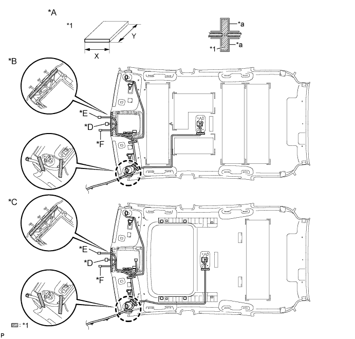
| *A | Tape Attachment Locations (Reference) | *B | w/o Sliding Roof |
| *C | w/ Sliding Roof | *D | w/ EC Mirror |
| *E | w/ Rain Sensor (for LHD), w/ Humidity Sensor (for RHD) | *F | w/ Humidity Sensor (for LHD), w/ Rain Sensor (for RHD) |
| *1 | Adhesive Tape | - | - |
| *a | Marking | - | - |
| 7. INSTALL NO. 2 ANTENNA CORD SUB-ASSEMBLY |
Apply new double-sided tape.
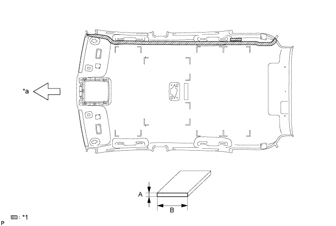
| *1 | Double-sided Tape | - | - |
| *a | Front Side | - | - |
Remove the old double-sided tape from the roof headlining assembly.
Prepare the appropriate amount of new double-sided tape.
| Area | Dimension |
| A | 1.0 mm (0.0394 in.) |
| B | 15.0 mm (0.591 in.) |
Apply the double-sided tape to the roof headlining while aligning the tape with the markings on the roof headlining assembly.
Peel off the release paper from the double-sided tape.
Install the No. 2 antenna cord sub-assembly to the roof headlining assembly from the front of the vehicle.
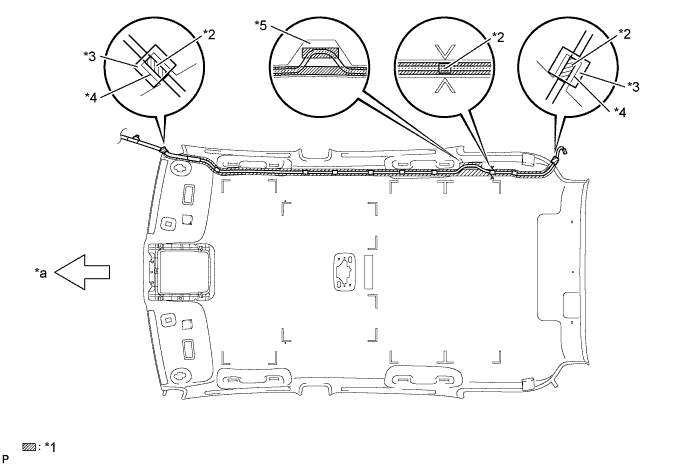
| *1 | Double-sided Tape | *2 | Marking Tape |
| *3 | Tape | *4 | Protrusion |
| *5 | Adjustment Area | - | - |
| *a | Front Side | - | - |
Put the strips of the tape back to the positions shown in the illustration in order to secure the antenna cord to the roof headlining assembly.
| 8. INSTALL VANITY LIGHT ASSEMBLY |
Install the vanity light assembly .