Home Engine / Hybrid System HYBRID / BATTERY CONTROL HYBRID CONTROL SYSTEM

DTC    P082B-575    Gear Lever X Position Circuit Low

DTC    P082C-576    Gear Lever X Position Circuit High

DTC    P082E-571    Gear Lever Y Position Circuit Low

DTC    P082F-572    Gear Lever Y Position Circuit High

DTC    P181A-596    Gear Lever X Position Circuit "A" / "B" Correlation

DTC    P181B-595    Gear Lever Y Position Circuit "A" / "B" Correlation

DTC    P182B-577    Gear Lever X Position "B" Circuit Low

DTC    P182C-578    Gear Lever X Position "B" Circuit High

DTC    P182E-573    Gear Lever Y Position "B" Circuit Low

DTC    P182F-574    Gear Lever Y Position "B" Circuit High

for Preparation Click here


DESCRIPTION

HINT:
  1. The electronic shift lever system is a linkless type that does not use a shift cable.
  2. The shift and select sensors are non-contact type sensors.


  1. The shift lever (transmission instrument panel shift assembly) is a momentary type, which returns to its home position by spring reaction as the driver's hand is released from the shift lever after shifting.
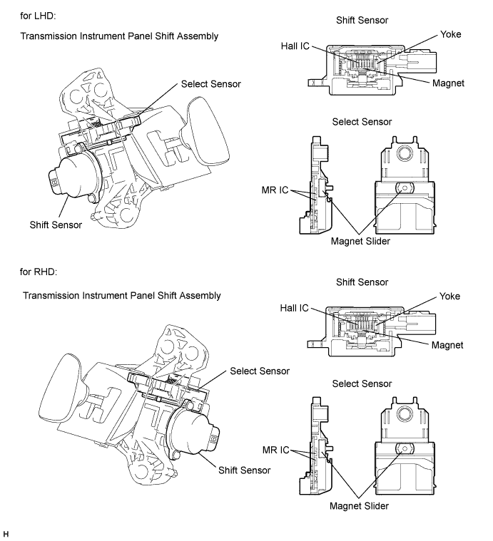
    The shift lever (transmission instrument panel shift assembly) contains a shift sensor and a select sensor to detect the shift lever position (Home, R, N, D or B). Because the shift sensor operates using Hall ICs and the select sensor operates using MR ICs, they can accurately detect the shift lever position in a reliable manner. Both sensors contain two detection circuits, a main and a sub circuit.


    C233780E01


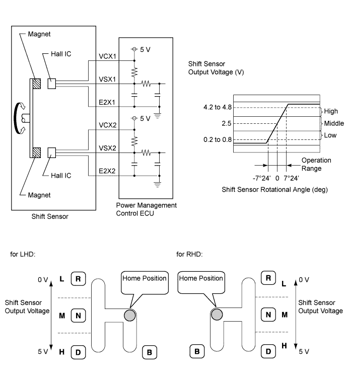
  2. The shift sensor outputs voltage, which varies between 0 and 5 V in accordance with the vertical movement of the shift lever, to the power management control ECU (HV CPU). The power management control ECU (HV CPU) interprets low level voltage input from the shift sensor as the R position, middle level voltage as the home or N position, and high level voltage as the D or B position.


    A221567E01


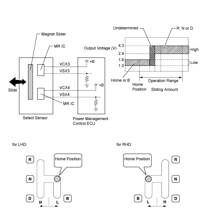
  3. The select sensor outputs voltage, which varies between 0 and 5 V in accordance with the horizontal movement of the shift lever, to the power management control ECU (HV CPU). The power management control ECU (HV CPU) interprets low level voltage input from the select sensor as the home or B position, and high level voltage as the R, N, or D position.
    The power management control ECU (HV CPU) determines the position of the shift lever in accordance with the combination of the signals from the shift sensor and select sensor.


    A221568E02


DTC No.
INF Code
DTC Detection Condition
Trouble Area
P082B
575
Open or GND short in select main sensor circuit
  1. Wire harness or connector
  2. Transmission instrument panel shift assembly
  3. Power management control ECU
P082C
576
+B short in select main sensor circuit
P082E
571
Open or GND short in shift main sensor circuit
P082F
572
+B short in shift main sensor circuit
P181A
596
Difference between select main sensor value and select sub sensor value is large
P181B
595
Difference between shift main sensor value and shift sub sensor value is large
P182B
577
Open or GND short in select sub sensor circuit
P182C
578
+B short in select sub sensor circuit
P182E
573
Open or GND short in shift sub sensor circuit
P182F
574
+B short in shift sub sensor circuit

HINT:
When any of DTCs P082E-571, P082F-572, P182E-573 or P182F-574 are output, check Shift Sensor Main and Shift Sensor Sub voltages using the intelligent tester.


Shift Sensor Main, Shift Sensor Sub 
R position
(Main)
Home or N position
(Main)
D or B position
(Main)
R position
(Sub)
Home or N position
(Sub)
D or B position
(Sub)
Trouble Area
0.3 to 1.8 V
2.0 to 3.0 V
3.2 to 4.8 V
0.3 to 1.8 V
2.0 to 3.0 V
3.2 to 4.8 V
Correct shift sensor voltage
0 to 0.3 V
0 to 0.3 V
0 to 0.3 V
0.3 to 1.8 V
2.0 to 3.0 V
3.2 to 4.8 V
Open in VCX1 circuit
GND short in VSX1 circuit
0.3 to 1.8 V
2.0 to 3.0 V
3.2 to 4.8 V
0 to 0.3 V
0 to 0.3 V
0 to 0.3 V
Open in VCX2 circuit
GND short in VSX2 circuit
4.8 to 5.0 V
4.8 to 5.0 V
4.8 to 5.0 V
0.3 to 1.8 V
2.0 to 3.0 V
3.2 to 4.8 V
Open in VSX1 circuit
Open in E2X1 circuit
0.3 to 1.8 V
2.0 to 3.0 V
3.2 to 4.8 V
4.8 to 5.0 V
4.8 to 5.0 V
4.8 to 5.0 V
Open in VSX2 circuit
Open in E2X2 circuit

HINT:
When any of DTCs P082B-575, P082C-576, P182B-577 or P182C-578 are output, check Shift Sensor Select Main and Shift Sensor Select Sub voltages using the intelligent tester.


Shift Sensor Select Main, Shift Sensor Select Sub 
R, N or D Position
Select Main)
Home or B Position
Select Main)
R, N or D Position
Select Sub)
Home or B Position
Select Sub)
Trouble Area
2.9 to 4.3 V
1.0 to 1.6 V
2.9 to 4.3 V
1.0 to 1.6 V
Correct select sensor voltage
0 to 0.5 V
0 to 0.5 V
2.9 to 4.3 V
1.0 to 1.6 V
Open in VCX3 circuit
Open or GND short in VSX3 circuit
2.9 to 4.3 V
1.0 to 1.6 V
0 to 0.5 V
0 to 0.5 V
Open in VCX4 circuit
Open or GND short in VSX4 circuit
4.9 to 5.0 V
4.9 to 5.0 V
2.9 to 4.3 V
1.0 to 1.6 V
+B short in VSX3 circuit
2.9 to 4.3 V
1.0 to 1.6 V
4.9 to 5.0 V
4.9 to 5.0 V
+B short in VSX4 circuit

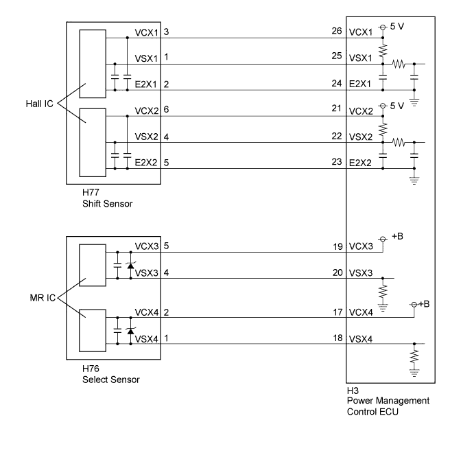
WIRING DIAGRAM


A220118E09

Refer to the wiring diagram for DTC P0AE6-225 .

INSPECTION PROCEDURE

1.READ VALUE USING INTELLIGENT TESTER (SHIFT SENSOR MAIN, SHIFT SENSOR SUB)
  1. Connect the intelligent tester to the DLC3.

  1. Turn the power switch on (IG).

  1. Enter the following menus: Powertrain / Hybrid Control / Data List / Shift Sensor Main, Shift Sensor Sub.

  1. Read the Data List.

    Result:
    Tester Display
    Condition
    Specified Condition
    Shift Sensor Main
    R position
    0.3 to 1.8 V
    Home or N position
    2.0 to 3.0 V
    D or B position
    3.2 to 4.8 V
    Shift Sensor Sub
    R position
    0.3 to 1.8 V
    Home or N position
    2.0 to 3.0 V
    D or B position
    3.2 to 4.8 V

  1. Turn the power switch off.


NG
Go to step 6
OK


2.READ VALUE USING INTELLIGENT TESTER (SHIFT SENSOR SELECT MAIN, SHIFT SENSOR SELECT SUB)
  1. Connect the intelligent tester to the DLC3.

  1. Turn the power switch on (IG).

  1. Enter the following menus: Powertrain / Hybrid Control / Data List / Shift Sensor Select Main, Shift Sensor Select Sub.

  1. Read the Data List.

    Result:
    Tester Display
    Condition
    Specified Condition
    Shift Sensor Select Main
    R, N or D Position
    2.9 to 4.3 V
    Home or B Position
    1.0 to 1.6 V
    Shift Sensor Select Sub
    R, N or D Position
    2.9 to 4.3 V
    Home or B Position
    1.0 to 1.6 V

  1. Turn the power switch off.


NG
Go to step 12
OK


3.REPLACE TRANSMISSION INSTRUMENT PANEL SHIFT ASSEMBLY
  1. Replace the transmission instrument panel shift assembly (Click here).


NEXT


4.CLEAR DTC
  1. Connect the intelligent tester to the DLC3.

  1. Turn the power switch on (IG).

  1. Enter the following menus: Powertrain / Hybrid Control / DTC.

  1. Read and record the DTCs and freeze frame data.

  1. Clear DTCs and freeze frame data.

  1. Turn the power switch off.


NEXT


5.CHECK DTC OUTPUT (HYBRID CONTROL)
  1. Connect the intelligent tester to the DLC3.

  1. Turn the power switch on (IG).

  1. Perform a road test.

  1. Enter the following menus: Powertrain / Hybrid Control / DTC.

  1. Check if DTCs are output.

    Result:
    Result
    Proceed to
    No DTCs are output.
    A
    P082B-575, P082C-576, P082E-571, P082F-572, P181A-596, P181B-595, P182B-577, P182C-578, P182E-573 or P182F-574 is output again.
    B

  1. Turn the power switch off.


B
REPLACE POWER MANAGEMENT CONTROL ECU (Click here)
A

COMPLETED 

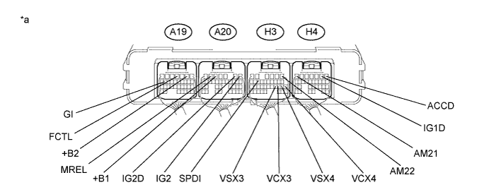
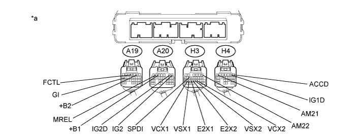
6.CHECK HARNESS AND CONNECTOR (+B SHORT)


    A248780E01
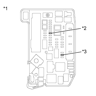
  1. Remove the IGCT NO. 2 fuse and AM2 fuse from the engine room junction block assembly.
    Text in Illustration 
    *1
    Engine Room Junction Block Assembly
    *2
    AM2 Fuse
    *3
    IGCT NO. 2 Fuse

  1. Disconnect connector H77 from the shift sensor.


  1. Measure the resistance according to the value(s) in the table below.


    A245294E07


    Text in Illustration 
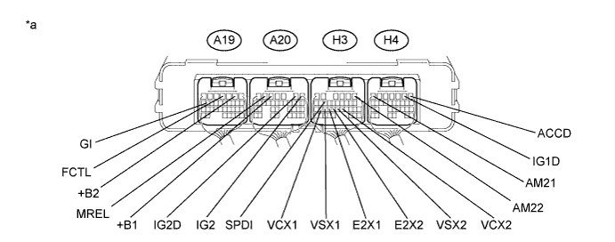
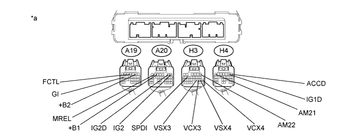
    *a
    Component with harness connected
    (Power Management Control ECU)
    -
    -

    Standard Resistance:

    Tester Connection
    Switch Condition
    Specified Condition
    H3-26 (VCX1) - A19-2 (+B2)
    Power switch off
    10 kΩ or higher
    H3-26 (VCX1) - A20-5 (+B1)
    Power switch off
    10 kΩ or higher
    H3-26 (VCX1) - H3-1 (AM22)
    Power switch off
    10 kΩ or higher
    H3-26 (VCX1) - H4-7 (AM21)
    Power switch off
    10 kΩ or higher
    H3-26 (VCX1) - A20-6 (MREL)
    Power switch off
    10 kΩ or higher
    H3-26 (VCX1) - A20-1 (IG2)
    Power switch off
    10 kΩ or higher
    H3-26 (VCX1) - H4-1 (ACCD)
    Power switch off
    10 kΩ or higher
    H3-26 (VCX1) - H4-2 (IG1D)
    Power switch off
    10 kΩ or higher
    H3-26 (VCX1) - A20-2 (IG2D)
    Power switch off
    10 kΩ or higher
    H3-26 (VCX1) - H3-14 (SPDI)
    Power switch off
    10 kΩ or higher
    H3-26 (VCX1) - A19-16 (GI)
    Power switch off
    10 kΩ or higher
    H3-26 (VCX1) - A19-4 (FCTL)
    Power switch off
    10 kΩ or higher


    Standard Resistance:

    Tester Connection
    Switch Condition
    Specified Condition
    H3-25 (VSX1) - A19-2 (+B2)
    Power switch off
    10 kΩ or higher
    H3-25 (VSX1) - A20-5 (+B1)
    Power switch off
    10 kΩ or higher
    H3-25 (VSX1) - H3-1 (AM22)
    Power switch off
    10 kΩ or higher
    H3-25 (VSX1) - H4-7 (AM21)
    Power switch off
    10 kΩ or higher
    H3-25 (VSX1) - A20-6 (MREL)
    Power switch off
    10 kΩ or higher
    H3-25 (VSX1) - A20-1 (IG2)
    Power switch off
    10 kΩ or higher
    H3-25 (VSX1) - H4-1 (ACCD)
    Power switch off
    10 kΩ or higher
    H3-25 (VSX1) - H4-2 (IG1D)
    Power switch off
    10 kΩ or higher
    H3-25 (VSX1) - A20-2 (IG2D)
    Power switch off
    10 kΩ or higher
    H3-25 (VSX1) - H3-14 (SPDI)
    Power switch off
    10 kΩ or higher
    H3-25 (VSX1) - A19-16 (GI)
    Power switch off
    10 kΩ or higher
    H3-25 (VSX1) - A19-4 (FCTL)
    Power switch off
    10 kΩ or higher


    Standard Resistance:

    Tester Connection
    Switch Condition
    Specified Condition
    H3-24 (E2X1) - A19-2 (+B2)
    Power switch off
    10 kΩ or higher
    H3-24 (E2X1) - A20-5 (+B1)
    Power switch off
    10 kΩ or higher
    H3-24 (E2X1) - H3-1 (AM22)
    Power switch off
    10 kΩ or higher
    H3-24 (E2X1) - H4-7 (AM21)
    Power switch off
    10 kΩ or higher
    H3-24 (E2X1) - A20-6 (MREL)
    Power switch off
    10 kΩ or higher
    H3-24 (E2X1) - A20-1 (IG2)
    Power switch off
    10 kΩ or higher
    H3-24 (E2X1) - H4-1 (ACCD)
    Power switch off
    10 kΩ or higher
    H3-24 (E2X1) - H4-2 (IG1D)
    Power switch off
    10 kΩ or higher
    H3-24 (E2X1) - A20-2 (IG2D)
    Power switch off
    10 kΩ or higher
    H3-24 (E2X1) - H3-14 (SPDI)
    Power switch off
    10 kΩ or higher
    H3-24 (E2X1) - A19-16 (GI)
    Power switch off
    10 kΩ or higher
    H3-24 (E2X1) - A19-4 (FCTL)
    Power switch off
    10 kΩ or higher


    Standard Resistance:

    Tester Connection
    Switch Condition
    Specified Condition
    H3-21 (VCX2) - A19-2 (+B2)
    Power switch off
    10 kΩ or higher
    H3-21 (VCX2) - A20-5 (+B1)
    Power switch off
    10 kΩ or higher
    H3-21 (VCX2) - H3-1 (AM22)
    Power switch off
    10 kΩ or higher
    H3-21 (VCX2) - H4-7 (AM21)
    Power switch off
    10 kΩ or higher
    H3-21 (VCX2) - A20-6 (MREL)
    Power switch off
    10 kΩ or higher
    H3-21 (VCX2) - A20-1 (IG2)
    Power switch off
    10 kΩ or higher
    H3-21 (VCX2) - H4-1 (ACCD)
    Power switch off
    10 kΩ or higher
    H3-21 (VCX2) - H4-2 (IG1D)
    Power switch off
    10 kΩ or higher
    H3-21 (VCX2) - A20-2 (IG2D)
    Power switch off
    10 kΩ or higher
    H3-21 (VCX2) - H3-14 (SPDI)
    Power switch off
    10 kΩ or higher
    H3-21 (VCX2) - A19-16 (GI)
    Power switch off
    10 kΩ or higher
    H3-21 (VCX2) - A19-4 (FCTL)
    Power switch off
    10 kΩ or higher


    Standard Resistance:

    Tester Connection
    Switch Condition
    Specified Condition
    H3-22 (VSX2) - A19-2 (+B2)
    Power switch off
    10 kΩ or higher
    H3-22 (VSX2) - A20-5 (+B1)
    Power switch off
    10 kΩ or higher
    H3-22 (VSX2) - H3-1 (AM22)
    Power switch off
    10 kΩ or higher
    H3-22 (VSX2) - H4-7 (AM21)
    Power switch off
    10 kΩ or higher
    H3-22 (VSX2) - A20-6 (MREL)
    Power switch off
    10 kΩ or higher
    H3-22 (VSX2) - A20-1 (IG2)
    Power switch off
    10 kΩ or higher
    H3-22 (VSX2) - H4-1 (ACCD)
    Power switch off
    10 kΩ or higher
    H3-22 (VSX2) - H4-2 (IG1D)
    Power switch off
    10 kΩ or higher
    H3-22 (VSX2) - A20-2 (IG2D)
    Power switch off
    10 kΩ or higher
    H3-22 (VSX2) - H3-14 (SPDI)
    Power switch off
    10 kΩ or higher
    H3-22 (VSX2) - A19-16 (GI)
    Power switch off
    10 kΩ or higher
    H3-22 (VSX2) - A19-4 (FCTL)
    Power switch off
    10 kΩ or higher


    Standard Resistance:

    Tester Connection
    Switch Condition
    Specified Condition
    H3-23 (E2X2) - A19-2 (+B2)
    Power switch off
    10 kΩ or higher
    H3-23 (E2X2) - A20-5 (+B1)
    Power switch off
    10 kΩ or higher
    H3-23 (E2X2) - H3-1 (AM22)
    Power switch off
    10 kΩ or higher
    H3-23 (E2X2) - H4-7 (AM21)
    Power switch off
    10 kΩ or higher
    H3-23 (E2X2) - A20-6 (MREL)
    Power switch off
    10 kΩ or higher
    H3-23 (E2X2) - A20-1 (IG2)
    Power switch off
    10 kΩ or higher
    H3-23 (E2X2) - H4-1 (ACCD)
    Power switch off
    10 kΩ or higher
    H3-23 (E2X2) - H4-2 (IG1D)
    Power switch off
    10 kΩ or higher
    H3-23 (E2X2) - A20-2 (IG2D)
    Power switch off
    10 kΩ or higher
    H3-23 (E2X2) - H3-14 (SPDI)
    Power switch off
    10 kΩ or higher
    H3-23 (E2X2) - A19-16 (GI)
    Power switch off
    10 kΩ or higher
    H3-23 (E2X2) - A19-4 (FCTL)
    Power switch off
    10 kΩ or higher

  1. Connect the shift sensor connector.

  1. Install the IGCT NO. 2 fuse and AM2 fuse.


NG
Go to step 18
OK


7.CHECK HARNESS AND CONNECTOR (POWER MANAGEMENT CONTROL ECU - SHIFT SENSOR)
  1. Disconnect connector H3 from the power management control ECU.

  1. Disconnect connector H77 from the shift sensor.


    A217101E05
  1. Measure the resistance according to the value(s) in the table below.

    Standard Resistance (Check for Open):
    Tester Connection
    Switch Condition
    Specified Condition
    H3-26 (VCX1) - H77-3 (VCX1)
    Power switch off
    Below 1 Ω
    H3-25 (VSX1) - H77-1 (VSX1)
    Power switch off
    Below 1 Ω
    H3-24 (E2X1) - H77-2 (E2X1)
    Power switch off
    Below 1 Ω
    H3-21 (VCX2) - H77-6 (VCX2)
    Power switch off
    Below 1 Ω
    H3-22 (VSX2) - H77-4 (VSX2)
    Power switch off
    Below 1 Ω
    H3-23 (E2X2) - H77-5 (E2X2)
    Power switch off
    Below 1 Ω

    Standard Resistance (Check for Short):
    Tester Connection
    Switch Condition
    Specified Condition
    H3-26 (VCX1) or H77-3 (VCX1) - Body ground and other terminals
    Power switch off
    10 kΩ or higher
    H3-25 (VSX1) or H77-1 (VSX1) - Body ground and other terminals
    Power switch off
    10 kΩ or higher
    H3-24 (E2X1) or H77-2 (E2X1) - Body ground and other terminals
    Power switch off
    10 kΩ or higher
    H3-21 (VCX2) or H77-6 (VCX2) - Body ground and other terminals
    Power switch off
    10 kΩ or higher
    H3-22 (VSX2) or H77-4 (VSX2) - Body ground and other terminals
    Power switch off
    10 kΩ or higher
    H3-23 (E2X2) or H77-5 (E2X2) - Body ground and other terminals
    Power switch off
    10 kΩ or higher

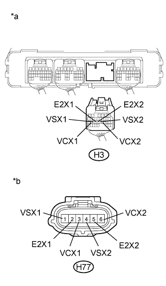
    Text in Illustration 
    *a
    Rear view of wire harness connector
    (to Power Management Control ECU)
    *b
    Front view of wire harness connector
    (to Shift Sensor)

    HINT:
    As necessary, check that there is no short to power supply wires when performing the above wire harness inspection.

  1. Connect the shift sensor connector.

  1. Connect the power management control ECU connector.


NG
REPAIR OR REPLACE HARNESS OR CONNECTOR
OK


8.CHECK POWER MANAGEMENT CONTROL ECU (VCX1, VCX2 VOLTAGE)
  1. Disconnect connector H77 from the shift sensor.

  1. Turn the power switch on (IG).


    A216508E08
  1. Measure the voltage according to the value(s) in the table below.

    Standard Voltage:
    Tester Connection
    Switch Condition
    Specified Condition
    H77-3 (VCX1) - H77-2 (E2X1)
    Power switch on (IG)
    4.5 to 5.5 V
    H77-6 (VCX2) - H77-5 (E2X2)
    Power switch on (IG)
    4.5 to 5.5 V

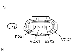
    Text in Illustration 
    *a
    Front view of wire harness connector
    (to Shift Sensor)

  1. Connect the shift sensor connector.


NG
REPLACE POWER MANAGEMENT CONTROL ECU (Click here)
OK


9.REPLACE TRANSMISSION INSTRUMENT PANEL SHIFT ASSEMBLY
  1. Replace the transmission instrument panel shift assembly (Click here).


NEXT


10.CLEAR DTC
  1. Connect the intelligent tester to the DLC3.

  1. Turn the power switch on (IG).

  1. Enter the following menus: Powertrain / Hybrid Control / DTC.

  1. Read and record the DTCs and freeze frame data.

  1. Clear DTCs and freeze frame data.

  1. Turn the power switch off.


NEXT


11.CHECK DTC OUTPUT (HYBRID CONTROL)
  1. Connect the intelligent tester to the DLC3.

  1. Turn the power switch on (IG).

  1. Perform a road test.

  1. Enter the following menus: Powertrain / Hybrid Control / DTC.

  1. Check if DTCs are output.

    Result:
    Result
    Proceed to
    No DTCs are output.
    A
    P082B-575, P082C-576, P082E-571, P082F-572, P181A-596, P181B-595, P182B-577, P182C-578, P182E-573 or P182F-574 is output again.
    B

  1. Turn the power switch off.


B
REPLACE POWER MANAGEMENT CONTROL ECU (Click here)
A

COMPLETED 

12.CHECK HARNESS AND CONNECTOR (+B SHORT)


    A248780E01
  1. Remove the IGCT NO. 2 fuse and AM2 fuse from the engine room junction block assembly.
    Text in Illustration 
    *1
    Engine Room Junction Block Assembly
    *2
    AM2 Fuse
    *3
    IGCT NO. 2 Fuse

  1. Disconnect connector H76 from the select sensor.


  1. Measure the resistance according to the value(s) in the table below.


    A245294E08


    Text in Illustration 
    *a
    Component with harness connected
    (Power Management Control ECU)
    -
    -

    Standard Resistance:

    Tester Connection
    Switch Condition
    Specified Condition
    H3-19 (VCX3) - A19-2 (+B2)
    Power switch off
    10 kΩ or higher
    H3-19 (VCX3) - A20-5 (+B1)
    Power switch off
    10 kΩ or higher
    H3-19 (VCX3) - H3-1 (AM22)
    Power switch off
    10 kΩ or higher
    H3-19 (VCX3) - H4-7 (AM21)
    Power switch off
    10 kΩ or higher
    H3-19 (VCX3) - A20-6 (MREL)
    Power switch off
    10 kΩ or higher
    H3-19 (VCX3) - A20-1 (IG2)
    Power switch off
    10 kΩ or higher
    H3-19 (VCX3) - H4-1 (ACCD)
    Power switch off
    10 kΩ or higher
    H3-19 (VCX3) - H4-2 (IG1D)
    Power switch off
    10 kΩ or higher
    H3-19 (VCX3) - A20-2 (IG2D)
    Power switch off
    10 kΩ or higher
    H3-19 (VCX3) - H3-14 (SPDI)
    Power switch off
    10 kΩ or higher
    H3-19 (VCX3) - A19-16 (GI)
    Power switch off
    10 kΩ or higher
    H3-19 (VCX3) - A19-4 (FCTL)
    Power switch off
    10 kΩ or higher


    Standard Resistance:

    Tester Connection
    Switch Condition
    Specified Condition
    H3-20 (VSX3) - A19-2 (+B2)
    Power switch off
    10 kΩ or higher
    H3-20 (VSX3) - A20-5 (+B1)
    Power switch off
    10 kΩ or higher
    H3-20 (VSX3) - H3-1 (AM22)
    Power switch off
    10 kΩ or higher
    H3-20 (VSX3) - H4-7 (AM21)
    Power switch off
    10 kΩ or higher
    H3-20 (VSX3) - A20-6 (MREL)
    Power switch off
    10 kΩ or higher
    H3-20 (VSX3) - A20-1 (IG2)
    Power switch off
    10 kΩ or higher
    H3-20 (VSX3) - H4-1 (ACCD)
    Power switch off
    10 kΩ or higher
    H3-20 (VSX3) - H4-2 (IG1D)
    Power switch off
    10 kΩ or higher
    H3-20 (VSX3) - A20-2 (IG2D)
    Power switch off
    10 kΩ or higher
    H3-20 (VSX3) - H3-14 (SPDI)
    Power switch off
    10 kΩ or higher
    H3-20 (VSX3) - A19-16 (GI)
    Power switch off
    10 kΩ or higher
    H3-20 (VSX3) - A19-4 (FCTL)
    Power switch off
    10 kΩ or higher


    Standard Resistance:

    Tester Connection
    Switch Condition
    Specified Condition
    H3-17 (VCX4) - A19-2 (+B2)
    Power switch off
    10 kΩ or higher
    H3-17 (VCX4) - A20-5 (+B1)
    Power switch off
    10 kΩ or higher
    H3-17 (VCX4) - H3-1 (AM22)
    Power switch off
    10 kΩ or higher
    H3-17 (VCX4) - H4-7 (AM21)
    Power switch off
    10 kΩ or higher
    H3-17 (VCX4) - A20-6 (MREL)
    Power switch off
    10 kΩ or higher
    H3-17 (VCX4) - A20-1 (IG2)
    Power switch off
    10 kΩ or higher
    H3-17 (VCX4) - H4-1 (ACCD)
    Power switch off
    10 kΩ or higher
    H3-17 (VCX4) - H4-2 (IG1D)
    Power switch off
    10 kΩ or higher
    H3-17 (VCX4) - A20-2 (IG2D)
    Power switch off
    10 kΩ or higher
    H3-17 (VCX4) - H3-14 (SPDI)
    Power switch off
    10 kΩ or higher
    H3-17 (VCX4) - A19-16 (GI)
    Power switch off
    10 kΩ or higher
    H3-17 (VCX4) - A19-4 (FCTL)
    Power switch off
    10 kΩ or higher


    Standard Resistance:

    Tester Connection
    Switch Condition
    Specified Condition
    H3-18 (VSX4) - A19-2 (+B2)
    Power switch off
    10 kΩ or higher
    H3-18 (VSX4) - A20-5 (+B1)
    Power switch off
    10 kΩ or higher
    H3-18 (VSX4) - H3-1 (AM22)
    Power switch off
    10 kΩ or higher
    H3-18 (VSX4) - H4-7 (AM21)
    Power switch off
    10 kΩ or higher
    H3-18 (VSX4) - A20-6 (MREL)
    Power switch off
    10 kΩ or higher
    H3-18 (VSX4) - A20-1 (IG2)
    Power switch off
    10 kΩ or higher
    H3-18 (VSX4) - H4-1 (ACCD)
    Power switch off
    10 kΩ or higher
    H3-18 (VSX4) - H4-2 (IG1D)
    Power switch off
    10 kΩ or higher
    H3-18 (VSX4) - A20-2 (IG2D)
    Power switch off
    10 kΩ or higher
    H3-18 (VSX4) - H3-14 (SPDI)
    Power switch off
    10 kΩ or higher
    H3-18 (VSX4) - A19-16 (GI)
    Power switch off
    10 kΩ or higher
    H3-18 (VSX4) - A19-4 (FCTL)
    Power switch off
    10 kΩ or higher

  1. Connect the select sensor connector.

  1. Install the IGCT NO. 2 fuse and AM2 fuse.


NG
Go to step 19
OK


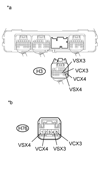
13.CHECK HARNESS AND CONNECTOR (POWER MANAGEMENT CONTROL ECU - SELECT SENSOR)
  1. Disconnect connector H3 from the power management control ECU.

  1. Disconnect connector H76 from the select sensor.


    A217100E04
  1. Measure the resistance according to the value(s) in the table below.

    Standard Resistance (Check for Open):
    Tester Connection
    Switch Condition
    Specified Condition
    H3-19 (VCX3) - H76-5 (VCX3)
    Power switch off
    Below 1 Ω
    H3-20 (VSX3) - H76-4 (VSX3)
    Power switch off
    Below 1 Ω
    H3-17 (VCX4) - H76-2 (VCX4)
    Power switch off
    Below 1 Ω
    H3-18 (VSX4) - H76-1 (VSX4)
    Power switch off
    Below 1 Ω

    Standard Resistance (Check for Short):
    Tester Connection
    Switch Condition
    Specified Condition
    H3-19 (VCX3) or H76-5 (VCX3) - Body ground and other terminals
    Power switch off
    10 kΩ or higher
    H3-20 (VSX3) or H76-4 (VSX3) - Body ground and other terminals
    Power switch off
    10 kΩ or higher
    H3-17 (VCX4) or H76-2 (VCX4) - Body ground and other terminals
    Power switch off
    10 kΩ or higher
    H3-18 (VSX4) or H76-1 (VSX4) - Body ground and other terminals
    Power switch off
    10 kΩ or higher

    Text in Illustration 
    *a
    Rear view of wire harness connector
    (to Power Management Control ECU)
    *b
    Front view of wire harness connector
    (to Select Sensor)

    HINT:
    As necessary, check that there is no short to power supply wires when performing the above wire harness inspection.

  1. Connect the select sensor connector.

  1. Connect the power management control ECU connector.


NG
REPAIR OR REPLACE HARNESS OR CONNECTOR
OK


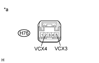
14.CHECK POWER MANAGEMENT CONTROL ECU (VCX3, VCX4 VOLTAGE)
  1. Disconnect connector H76 from the select sensor.

  1. Turn the power switch on (IG).


    A216507E06
  1. Measure the voltage according to the value(s) in the table below.

    Standard Voltage:
    Tester Connection
    Switch Condition
    Specified Condition
    H76-5 (VCX3) - Body ground
    Power switch on (IG)
    9 to 14 V
    H76-2 (VCX4) - Body ground
    Power switch on (IG)
    9 to 14 V

    Text in Illustration 
    *a
    Front view of wire harness connector
    (to Select Sensor)

  1. Connect the select sensor connector.


NG
REPLACE POWER MANAGEMENT CONTROL ECU (Click here)
OK


15.REPLACE TRANSMISSION INSTRUMENT PANEL SHIFT ASSEMBLY
  1. Replace the transmission instrument panel shift assembly (Click here).


NEXT


16.CLEAR DTC
  1. Connect the intelligent tester to the DLC3.

  1. Turn the power switch on (IG).

  1. Enter the following menus: Powertrain / Hybrid Control / DTC.

  1. Read and record the DTCs and freeze frame data.

  1. Clear DTCs and freeze frame data.

  1. Turn the power switch off.


NEXT


17.CHECK DTC OUTPUT (HYBRID CONTROL)
  1. Connect the intelligent tester to the DLC3.

  1. Turn the power switch on (IG).

  1. Perform a road test.

  1. Enter the following menus: Powertrain / Hybrid Control / DTC.

  1. Check if DTCs are output.

    Result:
    Result
    Proceed to
    No DTCs are output.
    A
    P082B-575, P082C-576, P082E-571, P082F-572, P181A-596, P181B-595, P182B-577, P182C-578, P182E-573 or P182F-574 is output again.
    B

  1. Turn the power switch off.


B
REPLACE POWER MANAGEMENT CONTROL ECU (Click here)
A

COMPLETED 

18.CHECK HARNESS AND CONNECTOR (SHORT TO POWER SUPPLY WIRES)


    A248780E01
  1. Remove the IGCT NO. 2 fuse and AM2 fuse from the engine room junction block assembly.
    Text in Illustration 
    *1
    Engine Room Junction Block Assembly
    *2
    AM2 Fuse
    *3
    IGCT NO. 2 Fuse

  1. Disconnect connector H77 from the shift sensor.

  1. Disconnect all the connectors from the power management control ECU.


  1. Measure the resistance according to the value(s) in the table below.


    A245299E09


    Text in Illustration 
    *a
    Rear view of wire harness connector
    (to Power Management Control ECU)
    -
    -

    Standard Resistance:

    Tester Connection
    Switch Condition
    Specified Condition
    H3-26 (VCX1) - A19-2 (+B2)
    Power switch off
    10 kΩ or higher
    H3-26 (VCX1) - A20-5 (+B1)
    Power switch off
    10 kΩ or higher
    H3-26 (VCX1) - H3-1 (AM22)
    Power switch off
    10 kΩ or higher
    H3-26 (VCX1) - H4-7 (AM21)
    Power switch off
    10 kΩ or higher
    H3-26 (VCX1) - A20-6 (MREL)
    Power switch off
    10 kΩ or higher
    H3-26 (VCX1) - A20-1 (IG2)
    Power switch off
    10 kΩ or higher
    H3-26 (VCX1) - H4-1 (ACCD)
    Power switch off
    10 kΩ or higher
    H3-26 (VCX1) - H4-2 (IG1D)
    Power switch off
    10 kΩ or higher
    H3-26 (VCX1) - A20-2 (IG2D)
    Power switch off
    10 kΩ or higher
    H3-26 (VCX1) - H3-14 (SPDI)
    Power switch off
    10 kΩ or higher
    H3-26 (VCX1) - A19-16 (GI)
    Power switch off
    10 kΩ or higher
    H3-26 (VCX1) - A19-4 (FCTL)
    Power switch off
    10 kΩ or higher


    Standard Resistance:

    Tester Connection
    Switch Condition
    Specified Condition
    H3-25 (VSX1) - A19-2 (+B2)
    Power switch off
    10 kΩ or higher
    H3-25 (VSX1) - A20-5 (+B1)
    Power switch off
    10 kΩ or higher
    H3-25 (VSX1) - H3-1 (AM22)
    Power switch off
    10 kΩ or higher
    H3-25 (VSX1) - H4-7 (AM21)
    Power switch off
    10 kΩ or higher
    H3-25 (VSX1) - A20-6 (MREL)
    Power switch off
    10 kΩ or higher
    H3-25 (VSX1) - A20-1 (IG2)
    Power switch off
    10 kΩ or higher
    H3-25 (VSX1) - H4-1 (ACCD)
    Power switch off
    10 kΩ or higher
    H3-25 (VSX1) - H4-2 (IG1D)
    Power switch off
    10 kΩ or higher
    H3-25 (VSX1) - A20-2 (IG2D)
    Power switch off
    10 kΩ or higher
    H3-25 (VSX1) - H3-14 (SPDI)
    Power switch off
    10 kΩ or higher
    H3-25 (VSX1) - A19-16 (GI)
    Power switch off
    10 kΩ or higher
    H3-25 (VSX1) - A19-4 (FCTL)
    Power switch off
    10 kΩ or higher


    Standard Resistance:

    Tester Connection
    Switch Condition
    Specified Condition
    H3-24 (E2X1) - A19-2 (+B2)
    Power switch off
    10 kΩ or higher
    H3-24 (E2X1) - A20-5 (+B1)
    Power switch off
    10 kΩ or higher
    H3-24 (E2X1) - H3-1 (AM22)
    Power switch off
    10 kΩ or higher
    H3-24 (E2X1) - H4-7 (AM21)
    Power switch off
    10 kΩ or higher
    H3-24 (E2X1) - A20-6 (MREL)
    Power switch off
    10 kΩ or higher
    H3-24 (E2X1) - A20-1 (IG2)
    Power switch off
    10 kΩ or higher
    H3-24 (E2X1) - H4-1 (ACCD)
    Power switch off
    10 kΩ or higher
    H3-24 (E2X1) - H4-2 (IG1D)
    Power switch off
    10 kΩ or higher
    H3-24 (E2X1) - A20-2 (IG2D)
    Power switch off
    10 kΩ or higher
    H3-24 (E2X1) - H3-14 (SPDI)
    Power switch off
    10 kΩ or higher
    H3-24 (E2X1) - A19-16 (GI)
    Power switch off
    10 kΩ or higher
    H3-24 (E2X1) - A19-4 (FCTL)
    Power switch off
    10 kΩ or higher


    Standard Resistance:

    Tester Connection
    Switch Condition
    Specified Condition
    H3-21 (VCX2) - A19-2 (+B2)
    Power switch off
    10 kΩ or higher
    H3-21 (VCX2) - A20-5 (+B1)
    Power switch off
    10 kΩ or higher
    H3-21 (VCX2) - H3-1 (AM22)
    Power switch off
    10 kΩ or higher
    H3-21 (VCX2) - H4-7 (AM21)
    Power switch off
    10 kΩ or higher
    H3-21 (VCX2) - A20-6 (MREL)
    Power switch off
    10 kΩ or higher
    H3-21 (VCX2) - A20-1 (IG2)
    Power switch off
    10 kΩ or higher
    H3-21 (VCX2) - H4-1 (ACCD)
    Power switch off
    10 kΩ or higher
    H3-21 (VCX2) - H4-2 (IG1D)
    Power switch off
    10 kΩ or higher
    H3-21 (VCX2) - A20-2 (IG2D)
    Power switch off
    10 kΩ or higher
    H3-21 (VCX2) - H3-14 (SPDI)
    Power switch off
    10 kΩ or higher
    H3-21 (VCX2) - A19-16 (GI)
    Power switch off
    10 kΩ or higher
    H3-21 (VCX2) - A19-4 (FCTL)
    Power switch off
    10 kΩ or higher


    Standard Resistance:

    Tester Connection
    Switch Condition
    Specified Condition
    H3-22 (VSX2) - A19-2 (+B2)
    Power switch off
    10 kΩ or higher
    H3-22 (VSX2) - A20-5 (+B1)
    Power switch off
    10 kΩ or higher
    H3-22 (VSX2) - H3-1 (AM22)
    Power switch off
    10 kΩ or higher
    H3-22 (VSX2) - H4-7 (AM21)
    Power switch off
    10 kΩ or higher
    H3-22 (VSX2) - A20-6 (MREL)
    Power switch off
    10 kΩ or higher
    H3-22 (VSX2) - A20-1 (IG2)
    Power switch off
    10 kΩ or higher
    H3-22 (VSX2) - H4-1 (ACCD)
    Power switch off
    10 kΩ or higher
    H3-22 (VSX2) - H4-2 (IG1D)
    Power switch off
    10 kΩ or higher
    H3-22 (VSX2) - A20-2 (IG2D)
    Power switch off
    10 kΩ or higher
    H3-22 (VSX2) - H3-14 (SPDI)
    Power switch off
    10 kΩ or higher
    H3-22 (VSX2) - A19-16 (GI)
    Power switch off
    10 kΩ or higher
    H3-22 (VSX2) - A19-4 (FCTL)
    Power switch off
    10 kΩ or higher


    Standard Resistance:

    Tester Connection
    Switch Condition
    Specified Condition
    H3-23 (E2X2) - A19-2 (+B2)
    Power switch off
    10 kΩ or higher
    H3-23 (E2X2) - A20-5 (+B1)
    Power switch off
    10 kΩ or higher
    H3-23 (E2X2) - H3-1 (AM22)
    Power switch off
    10 kΩ or higher
    H3-23 (E2X2) - H4-7 (AM21)
    Power switch off
    10 kΩ or higher
    H3-23 (E2X2) - A20-6 (MREL)
    Power switch off
    10 kΩ or higher
    H3-23 (E2X2) - A20-1 (IG2)
    Power switch off
    10 kΩ or higher
    H3-23 (E2X2) - H4-1 (ACCD)
    Power switch off
    10 kΩ or higher
    H3-23 (E2X2) - H4-2 (IG1D)
    Power switch off
    10 kΩ or higher
    H3-23 (E2X2) - A20-2 (IG2D)
    Power switch off
    10 kΩ or higher
    H3-23 (E2X2) - H3-14 (SPDI)
    Power switch off
    10 kΩ or higher
    H3-23 (E2X2) - A19-16 (GI)
    Power switch off
    10 kΩ or higher
    H3-23 (E2X2) - A19-4 (FCTL)
    Power switch off
    10 kΩ or higher

  1. Connect the power management control ECU connectors.

  1. Connect the shift sensor connector.

  1. Install the IGCT NO. 2 fuse and AM2 fuse.


NG
REPAIR OR REPLACE HARNESS OR CONNECTOR
OK

REPLACE POWER MANAGEMENT CONTROL ECU (Click here)  

19.CHECK HARNESS AND CONNECTOR (SHORT TO POWER SUPPLY WIRES)


    A248780E01
  1. Remove the IGCT NO. 2 fuse and AM2 fuse from the engine room junction block assembly.
    Text in Illustration 
    *1
    Engine Room Junction Block Assembly
    *2
    AM2 Fuse
    *3
    IGCT NO. 2 Fuse

  1. Disconnect connector H76 from the select sensor.

  1. Disconnect all the connectors from the power management control ECU.


  1. Measure the resistance according to the value(s) in the table below.


    A245299E10


    Text in Illustration 
    *a
    Rear view of wire harness connector
    (to Power Management Control ECU)
    -
    -

    Standard Resistance:

    Tester Connection
    Switch Condition
    Specified Condition
    H3-19 (VCX3) - A19-2 (+B2)
    Power switch off
    10 kΩ or higher
    H3-19 (VCX3) - A20-5 (+B1)
    Power switch off
    10 kΩ or higher
    H3-19 (VCX3) - H3-1 (AM22)
    Power switch off
    10 kΩ or higher
    H3-19 (VCX3) - H4-7 (AM21)
    Power switch off
    10 kΩ or higher
    H3-19 (VCX3) - A20-6 (MREL)
    Power switch off
    10 kΩ or higher
    H3-19 (VCX3) - A20-1 (IG2)
    Power switch off
    10 kΩ or higher
    H3-19 (VCX3) - H4-1 (ACCD)
    Power switch off
    10 kΩ or higher
    H3-19 (VCX3) - H4-2 (IG1D)
    Power switch off
    10 kΩ or higher
    H3-19 (VCX3) - A20-2 (IG2D)
    Power switch off
    10 kΩ or higher
    H3-19 (VCX3) - H3-14 (SPDI)
    Power switch off
    10 kΩ or higher
    H3-19 (VCX3) - A19-16 (GI)
    Power switch off
    10 kΩ or higher
    H3-19 (VCX3) - A19-4 (FCTL)
    Power switch off
    10 kΩ or higher


    Standard Resistance:

    Tester Connection
    Switch Condition
    Specified Condition
    H3-20 (VSX3) - A19-2 (+B2)
    Power switch off
    10 kΩ or higher
    H3-20 (VSX3) - A20-5 (+B1)
    Power switch off
    10 kΩ or higher
    H3-20 (VSX3) - H3-1 (AM22)
    Power switch off
    10 kΩ or higher
    H3-20 (VSX3) - H4-7 (AM21)
    Power switch off
    10 kΩ or higher
    H3-20 (VSX3) - A20-6 (MREL)
    Power switch off
    10 kΩ or higher
    H3-20 (VSX3) - A20-1 (IG2)
    Power switch off
    10 kΩ or higher
    H3-20 (VSX3) - H4-1 (ACCD)
    Power switch off
    10 kΩ or higher
    H3-20 (VSX3) - H4-2 (IG1D)
    Power switch off
    10 kΩ or higher
    H3-20 (VSX3) - A20-2 (IG2D)
    Power switch off
    10 kΩ or higher
    H3-20 (VSX3) - H3-14 (SPDI)
    Power switch off
    10 kΩ or higher
    H3-20 (VSX3) - A19-16 (GI)
    Power switch off
    10 kΩ or higher
    H3-20 (VSX3) - A19-4 (FCTL)
    Power switch off
    10 kΩ or higher


    Standard Resistance:

    Tester Connection
    Switch Condition
    Specified Condition
    H3-17 (VCX4) - A19-2 (+B2)
    Power switch off
    10 kΩ or higher
    H3-17 (VCX4) - A20-5 (+B1)
    Power switch off
    10 kΩ or higher
    H3-17 (VCX4) - H3-1 (AM22)
    Power switch off
    10 kΩ or higher
    H3-17 (VCX4) - H4-7 (AM21)
    Power switch off
    10 kΩ or higher
    H3-17 (VCX4) - A20-6 (MREL)
    Power switch off
    10 kΩ or higher
    H3-17 (VCX4) - A20-1 (IG2)
    Power switch off
    10 kΩ or higher
    H3-17 (VCX4) - H4-1 (ACCD)
    Power switch off
    10 kΩ or higher
    H3-17 (VCX4) - H4-2 (IG1D)
    Power switch off
    10 kΩ or higher
    H3-17 (VCX4) - A20-2 (IG2D)
    Power switch off
    10 kΩ or higher
    H3-17 (VCX4) - H3-14 (SPDI)
    Power switch off
    10 kΩ or higher
    H3-17 (VCX4) - A19-16 (GI)
    Power switch off
    10 kΩ or higher
    H3-17 (VCX4) - A19-4 (FCTL)
    Power switch off
    10 kΩ or higher


    Standard Resistance:

    Tester Connection
    Switch Condition
    Specified Condition
    H3-18 (VSX4) - A19-2 (+B2)
    Power switch off
    10 kΩ or higher
    H3-18 (VSX4) - A20-5 (+B1)
    Power switch off
    10 kΩ or higher
    H3-18 (VSX4) - H3-1 (AM22)
    Power switch off
    10 kΩ or higher
    H3-18 (VSX4) - H4-7 (AM21)
    Power switch off
    10 kΩ or higher
    H3-18 (VSX4) - A20-6 (MREL)
    Power switch off
    10 kΩ or higher
    H3-18 (VSX4) - A20-1 (IG2)
    Power switch off
    10 kΩ or higher
    H3-18 (VSX4) - H4-1 (ACCD)
    Power switch off
    10 kΩ or higher
    H3-18 (VSX4) - H4-2 (IG1D)
    Power switch off
    10 kΩ or higher
    H3-18 (VSX4) - A20-2 (IG2D)
    Power switch off
    10 kΩ or higher
    H3-18 (VSX4) - H3-14 (SPDI)
    Power switch off
    10 kΩ or higher
    H3-18 (VSX4) - A19-16 (GI)
    Power switch off
    10 kΩ or higher
    H3-18 (VSX4) - A19-4 (FCTL)
    Power switch off
    10 kΩ or higher

  1. Connect the power management control ECU connectors.

  1. Connect the select sensor connector.

  1. Install the IGCT NO. 2 fuse and AM2 fuse.


NG
REPAIR OR REPLACE HARNESS OR CONNECTOR
OK

REPLACE POWER MANAGEMENT CONTROL ECU (Click here)