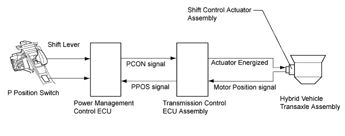
DTC P085D-582 Gear Shift Control Module "A" Performance |
DTC P085D-599 Gear Shift Control Module "A" Performance |
DTC P0861-597 Gear Shift Control Module "A" Communication Circuit Low |
DTC P0862-598 Gear Shift Control Module "A" Communication Circuit High |
| DTC No. | INF Code | DTC Detection Condition | Trouble Area |
| P085D | 582 | P position (PPOS) signal is logically inconsistent |
|
| 599 | P position (PPOS) signal malfunction (output pulse is abnormal) | ||
| P0861 | 597 | GND short in P position (PPOS) signal circuit | |
| P0862 | 598 | +B short in P position (PPOS) signal circuit |
| 1.CHECK DTC OUTPUT (TRANSMISSION CONTROL) |
Connect the intelligent tester to the DLC3.
Turn the power switch on (IG).
Enter the following menus: Chassis / Transmission Control / DTC.
Check if DTCs are output.
| Result | Proceed to |
| Electronic shift lever system DTCs are not output. | A |
| Any of the following DTCs are output. | B |
| DTC No. | Relevant Diagnosis |
| C2309 | Open in B+ Circuit |
| C2311 | Communication Error from HV ECU |
Turn the power switch off.
|
| ||||
| A | |
 |
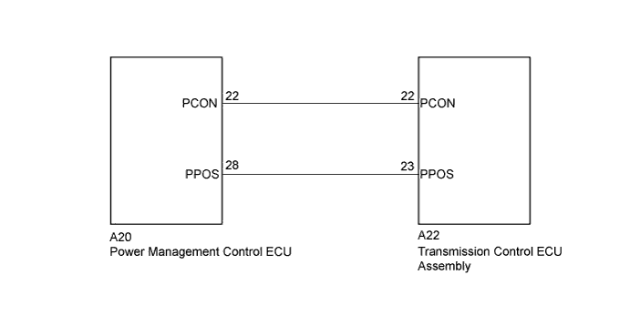
| 2.CHECK HARNESS AND CONNECTOR (POWER MANAGEMENT CONTROL ECU - TRANSMISSION CONTROL ECU) |
Disconnect connector A20 from the power management control ECU.
Disconnect connector A22 from the transmission control ECU assembly.
Turn the power switch on (IG).
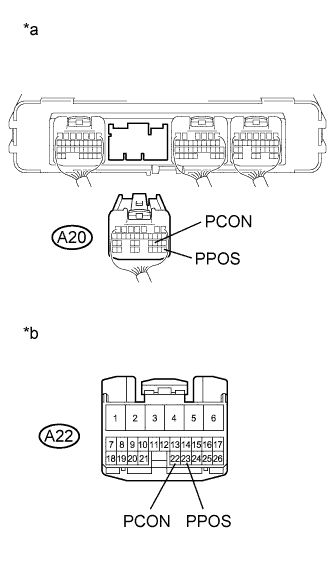 |
Measure the voltage according to the value(s) in the table below.
| Tester Connection | Switch Condition | Specified Condition |
| A22-22 (PCON) - Body ground | Power switch on (IG) | Below 1 V |
| A22-23 (PPOS) - Body ground | Power switch on (IG) | Below 1 V |
| *a | Rear view of wire harness connector (to Power Management Control ECU) |
| *b | Front view of wire harness connector (to Transmission Control ECU Assembly) |
Turn the power switch off.
Measure the resistance according to the value(s) in the table below.
| Tester Connection | Switch Condition | Specified Condition |
| A20-22 (PCON) - A22-22 (PCON) | Power switch off | Below 1 Ω |
| A20-28 (PPOS) - A22-23 (PPOS) | Power switch off | Below 1 Ω |
| Tester Connection | Switch Condition | Specified Condition |
| A20-22 (PCON) or A22-22 (PCON) - Body ground and other terminals | Power switch off | 10 kΩ or higher |
| A20-28 (PPOS) or A22-23 (PPOS) - Body ground and other terminals | Power switch off | 10 kΩ or higher |
Connect the transmission control ECU assembly connector.
Connect the power management control ECU connector.
|
| ||||
| OK | |
|
| 3.CHECK POWER MANAGEMENT CONTROL ECU (PCON SIGNAL) |
Turn the power switch on (IG).
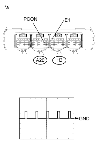 |
Connect an oscilloscope between the power management control ECU terminals specified in the table below, and measure the waveform.
| Item | Content |
| Terminal | A20-22 (PCON) - H3-6 (E1) |
| Equipment Setting | 10V/DIV., 10ms/DIV. |
| Condition | Power switch on (IG) |
| Result | Proceed to |
| P position control (PCON) signal waveform appears. | A |
| P position control (PCON) signal waveform does not appear. | B |
| *a | Component with harness connected (Power Management Control ECU) |
Turn the power switch off.
|
| ||||
| A | |
|
| 4.CHECK POWER MANAGEMENT CONTROL ECU (PPOS SIGNAL) |
Turn the power switch on (IG).
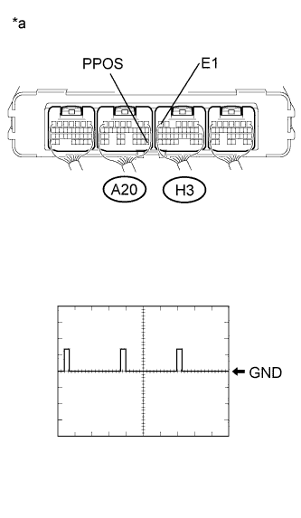 |
Connect an oscilloscope between the power management control ECU terminals specified in the table below, and measure the waveform.
| Item | Content |
| Terminal | A20-28 (PPOS) - H3-6 (E1) |
| Equipment Setting | 10V/DIV., 10ms/DIV. |
| Condition | Power switch on (IG) |
| Result | Proceed to |
| P position (PPOS) signal waveform appears | A |
| P position (PPOS) signal waveform does not appear | B |
| *a | Component with harness connected (Power Management Control ECU) |
Turn the power switch off.
|
| ||||
| A | |
|
| 5.REPLACE POWER MANAGEMENT CONTROL ECU |
Replace the power management control ECU (Click here).
| NEXT | |
|
| 6.CLEAR DTC |
Connect the intelligent tester to the DLC3.
Turn the power switch on (IG).
Enter the following menus: Powertrain / Hybrid Control / DTC.
Read and record the DTCs and freeze frame data.
Clear DTCs and freeze frame data.
Turn the power switch off.
| NEXT | |
|
| 7.CHECK DTC OUTPUT (HYBRID CONTROL) |
Connect the intelligent tester to the DLC3.
Turn the power switch on (IG) and leave the vehicle as it is for 10 seconds.
Depress the brake pedal, move the shift lever to N and leave the vehicle as it is for 10 seconds.
Push the P position switch (transmission shift main switch) and leave the vehicle as it is for 10 seconds.
Enter the following menus: Powertrain / Hybrid Control / DTC.
Check if DTCs are output.
| Result | Proceed to |
| No DTCs are output. | A |
| P085D-582, P085D-599, P0861-597 or P0862-598 is output again. | B |
Turn the power switch off.
|
| ||||
| A | ||
 | ||
| ||
