DTC B1503 Exhaust Heat Management Warning Detected |
| DTC No. | DTC Detection Condition | Trouble Area |
| B1503 | When IG voltage is 9.5 V or more and the following condition is detected:
|
|
| 1.READ VALUE USING INTELLIGENT TESTER |
Set the vehicle in the maintenance mode using the intelligent tester (Click here).
Connect the intelligent tester to the DLC3.
Turn the power switch on (IG).
Turn the intelligent tester on.
Enter the following menus: Body / Combination Meter / Data List.
Check the values by referring to the table below.
| Tester Display | Measurement Item/Range | Normal Condition | Diagnostic Note |
| Coolant Temperature | Engine coolant temperature/-40 to 127.5°C (-40 to 261.5°F) | After warming up: 75 to 100°C (167 to 212°F) |
|
|
| ||||
| OK | |
 |
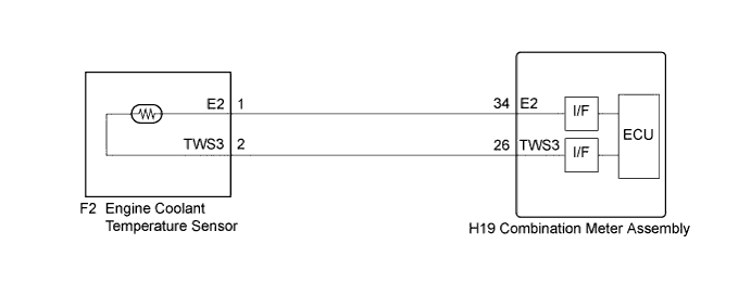
| 2.CHECK HARNESS AND CONNECTOR (COMBINATION METER - ENGINE COOLANT TEMPERATURE SENSOR) |
Disconnect the F2 connector.
Disconnect the H19 connector.
Measure the resistance according to the value(s) in the table below.
| Tester Connection | Condition | Specified Condition |
| F2-2 (TWS3) - H19-26 (TWS3) | Always | Below 1 Ω |
| F2-1 (E2) - H19-34 (E2) | Always | Below 1 Ω |
| F2-2 (TWS3) or H19-26 (TWS3) - Body ground | Always | 10 kΩ or higher |
|
| ||||
| OK | |
|
| 3.INSPECT ENGINE COOLANT TEMPERATURE SENSOR |
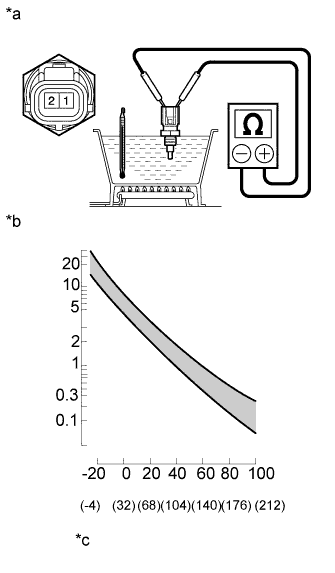 |
Remove the engine coolant temperature sensor (Click here).
Measure the resistance according to the value(s) in the table below.
| Tester Connection | Condition | Specified Condition |
| 1 (E2) - 2 (TWS3) | Temperature is 20°C (68°F) | 2.32 to 2.59 kΩ |
| 1 (E2) - 2 (TWS3) | Temperature is 80°C (176°F) | 0.310 to 0.326 kΩ |
| *a | Component without harness connected (Engine Coolant Temperature Sensor) |
| *b | Resistance kΩ |
| *c | Temperature °C (°F) |
|
| ||||
| OK | ||
 | ||
| ||
