 |
Remove the clip.
UPPER INSTRUMENT PANEL > REMOVAL |
| 1. PRECAUTION |
| 2. REMOVE REAR NO. 2 FLOOR BOARD |
Remove the rear No. 2 floor board.
| 3. REMOVE REAR DECK FLOOR BOX |
Remove the rear deck floor box.
| 4. REMOVE REAR NO. 3 FLOOR BOARD |
Remove the rear No. 3 floor board.
| 5. REMOVE DECK FLOOR BOX RH |
|
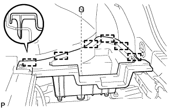
Remove the clip.
Disengage the 6 guides and remove the deck floor box RH.
| 6. REMOVE REAR FLOOR BOARD UPPER NO. 3 PLATE |
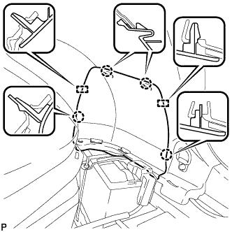 |
Disengage the 4 claws and 2 guides, and remove the rear floor board upper No. 3 plate.
| 7. DISCONNECT CABLE FROM NEGATIVE BATTERY TERMINAL |
| 8. REMOVE METER HOOD SUB-ASSEMBLY |
Operate the tilt and telescopic lever to fully extend and lower the steering column assembly.
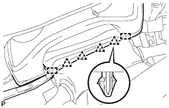 |
Using a moulding remover, disengage the 4 clips and 2 guides.
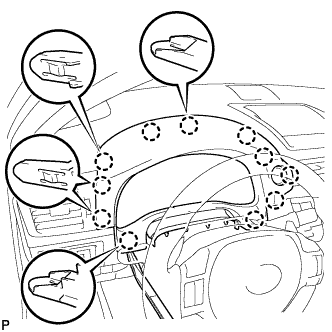 |
Using a moulding remover, disengage the 11 claws.
Disconnect the connector and remove the meter hood sub-assembly.
| 9. REMOVE COMBINATION METER ASSEMBLY |
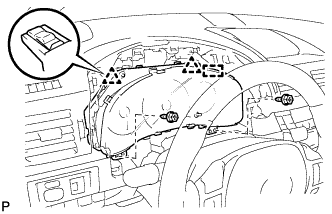 |
Disengage the clamp.
Remove the 2 screws.
Disengage the 2 clips.
Disconnect the connector and remove the combination meter assembly.
| 10. DISCONNECT FRONT DOOR OPENING TRIM WEATHERSTRIP LH |
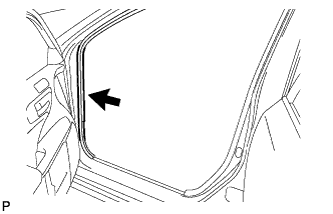 |
Disconnect the front door opening trim weatherstrip.
Remove the residual weatherstrip sealant from the body of the vehicle using cleaner.
| 11. REMOVE INSTRUMENT SIDE PANEL LH |
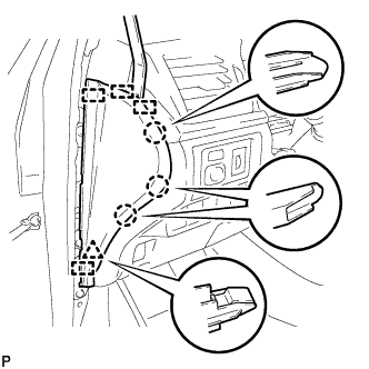 |
Using a moulding remover, disengage the 3 claws, clip and 4 guides, and remove the instrument side panel LH.
| 12. REMOVE LOWER INSTRUMENT PANEL FINISH PANEL SUB-ASSEMBLY |
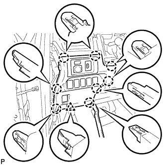 |
Using a moulding remover, disengage the 8 claws and clip.
Disconnect each connector and remove the lower instrument panel finish panel sub-assembly.
| 13. REMOVE FRONT PILLAR GARNISH LH |
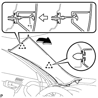 |
Pull the upper part of the garnish toward the inside of the cabin and disengage the 2 clips.
| *1 | Front Pillar Garnish Clip |
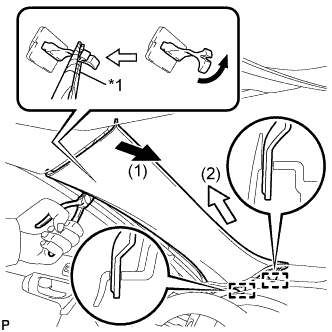 |
Turn the end of the front pillar garnish clip 90° with needle-nosed pliers and remove it from the front pillar garnish LH.
| *1 | Protective Tape |
Disengage the 2 guides.
w/o Front Center Speaker:
Remove the front pillar garnish LH by pulling it in the direction indicated by the arrow (2) in the illustration.
w/ Front Center Speaker:
Disconnect the front pillar garnish LH by pulling it in the direction indicated by the arrow (2) in the illustration.
Disconnect the connector and remove the front pillar garnish LH.
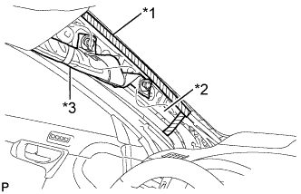 |
Protect the curtain shield airbag assembly.
| *1 | Adhesive Tape |
| *2 | Protective Cover |
| *3 | Curtain Shield Airbag Assembly |
Cover the airbag with a cloth or piece of nylon and secure the ends of the cover with tape as shown in the illustration.
| 14. REMOVE NO. 1 INSTRUMENT PANEL REGISTER ASSEMBLY |
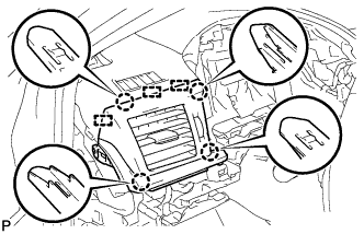 |
Disengage the 4 claws and 3 guides, and remove the No. 1 instrument panel register assembly.
| 15. REMOVE NO. 1 DEFROSTER NOZZLE OPENING PLATE |
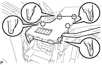 |
Using a moulding remover, disengage the 5 claws and remove the No. 1 defroster nozzle opening plate.
| 16. REMOVE NO. 2 INSTRUMENT PANEL SPEAKER PANEL SUB-ASSEMBLY |
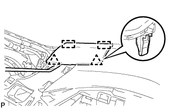 |
Using a moulding remover, disengage the 2 clips and 2 guides, and remove the No. 2 instrument panel speaker panel sub-assembly.
| 17. REMOVE FRONT NO. 2 SPEAKER ASSEMBLY (w/ Front No. 2 Speaker) |
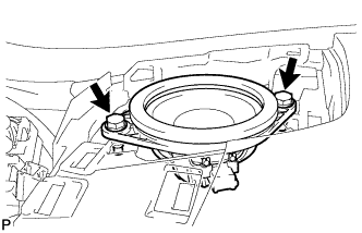 |
Remove the 2 bolts.
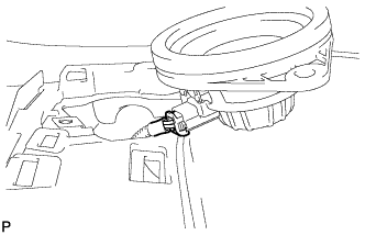 |
Lift the front No. 2 speaker assembly and disconnect the connector to remove the speaker.
| 18. DISCONNECT FRONT DOOR OPENING TRIM WEATHERSTRIP RH |
| 19. REMOVE INSTRUMENT SIDE PANEL RH |
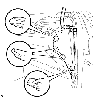 |
Using a moulding remover, disengage the 3 claws, clip and 4 guides, and remove the instrument side panel RH.
Disconnect the connector.
| 20. REMOVE NO. 2 INSTRUMENT PANEL UNDER COVER SUB-ASSEMBLY (for LHD) |
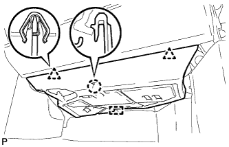 |
Disengage the 2 clips, claw and guide.
Disengage the clamp.
Disconnect the connector and remove the No. 2 instrument panel under cover sub-assembly.
| 21. REMOVE NO. 2 INSTRUMENT PANEL UNDER COVER SUB-ASSEMBLY (for RHD) |
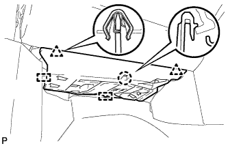 |
Disengage the 2 clips, claw and 2 guides.
Disengage the clamp.
Disconnect the connector and remove the No. 2 instrument panel under cover sub-assembly.
| 22. REMOVE FRONT DOOR SCUFF PLATE RH |
| 23. REMOVE COWL SIDE TRIM SUB-ASSEMBLY RH |
| 24. REMOVE LOWER NO. 2 INSTRUMENT PANEL AIRBAG ASSEMBLY |
Check that the power switch is off.
Check that the cable is disconnected from the negative (-) auxiliary battery terminal.
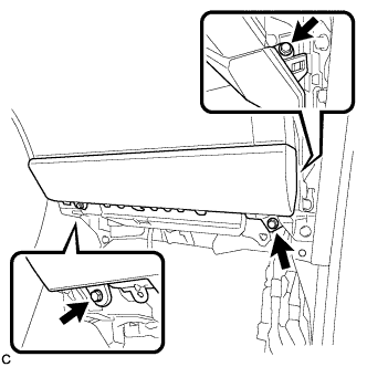 |
Remove the 3 bolts.
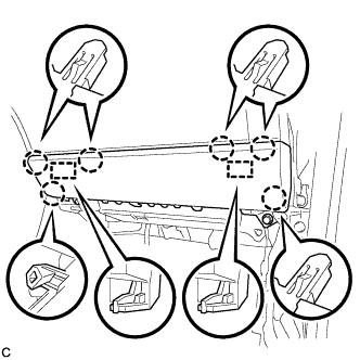 |
Disengage the 6 claws and 2 guides to separate the lower No. 2 instrument panel airbag assembly.
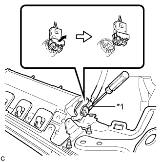 |
Using a screwdriver with the tip wrapped with protective tape, release the airbag connector lock.
| *1 | Protective Tape |
Disconnect the airbag connector to remove the lower No. 2 instrument panel airbag assembly.
| 25. REMOVE GLOVE COMPARTMENT DOOR ASSEMBLY |
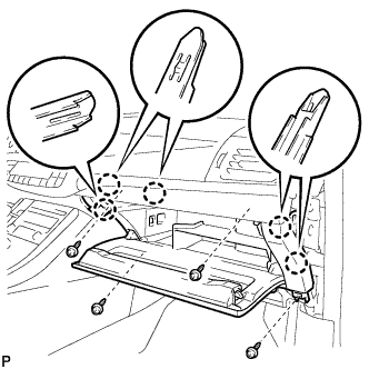 |
Remove the 4 screws <C>.
Disengage the 5 claws.
Disengage the clamp.
Disconnect the connector and remove the glove compartment door assembly.
| 26. REMOVE FRONT PILLAR GARNISH RH |
| 27. REMOVE NO. 3 INSTRUMENT CLUSTER FINISH PANEL GARNISH (for Metal Finish Panel and Urethane Panel) |
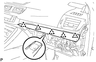 |
Disengage the 5 clips and remove the No. 3 instrument cluster finish panel garnish.
| 28. REMOVE NO. 3 INSTRUMENT CLUSTER FINISH PANEL GARNISH (for Wood Panel and Bamboo Panel) |
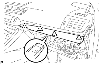 |
Disengage the 4 clips and remove the No. 3 instrument cluster finish panel garnish.
| 29. REMOVE NO. 2 INSTRUMENT PANEL REGISTER ASSEMBLY |
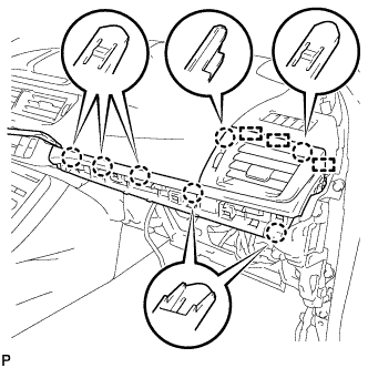 |
Using a moulding remover, disengage the 7 claws and 3 guides, and remove the No. 2 instrument panel register assembly.
| 30. REMOVE NO. 2 DEFROSTER NOZZLE OPENING PLATE |
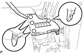 |
Using a moulding remover, disengage the 4 claws and remove the No. 2 defroster nozzle opening plate.
| 31. REMOVE NO. 1 INSTRUMENT PANEL SPEAKER PANEL SUB-ASSEMBLY |
| 32. REMOVE FRONT NO. 2 SPEAKER ASSEMBLY (w/ Front No. 2 Speaker) |
| 33. REMOVE NO. 1 SPEAKER OPENING COVER ASSEMBLY |
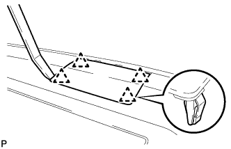 |
Using a moulding remover, disengage the 4 clips and remove the No. 1 speaker opening cover assembly.
| 34. REMOVE FRONT NO. 4 SPEAKER ASSEMBLY (w/ Front Center Speaker) |
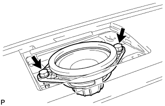 |
Remove the 2 bolts.
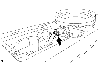 |
Lift the front No. 4 speaker assembly and disconnect the connector to remove the speaker.
| 35. REMOVE CENTER INSTRUMENT PANEL REGISTER ASSEMBLY |
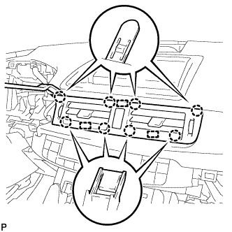 |
Using a moulding remover, disengage the 8 claws and 3 guides.
Disconnect the connector and remove the center instrument panel register assembly.
| 36. REMOVE INSTRUMENT CLUSTER FINISH PANEL SUB-ASSEMBLY (w/ Navigation System) |
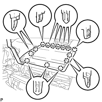 |
Using a moulding remover, disengage the 14 claws.
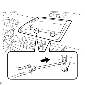 |
Using a screwdriver, disengage the 2 claws and remove the instrument cluster finish panel sub-assembly as shown in the illustration.
| 37. DISCONNECT NO. 3 INSTRUMENT PANEL WIRE |
Check that the power switch is off.
Check that the cable is disconnected from the negative (-) auxiliary battery terminal.
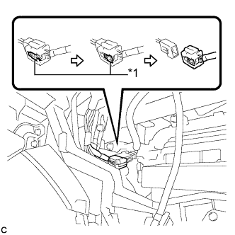 |
Slide the slider to release the lock, and then disconnect the connector.
| *1 | Slider |
| 38. REMOVE UPPER INSTRUMENT PANEL ASSEMBLY |
Disconnect each connector.
Disengage the clamp.
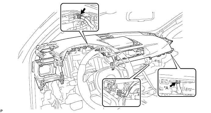
| *A | w/ Navigation System | - | - |
Remove the 2 bolts <A> and 2 screws <B>.
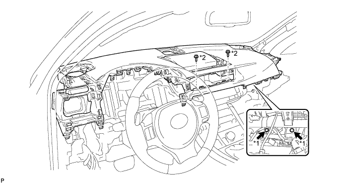
| *1 | Bolt <A> | *2 | Screw <B> |
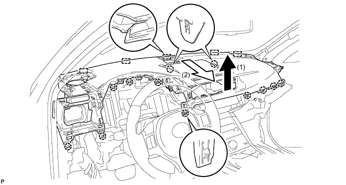
Disengage the 12 claws.
Disengage the 5 guides and remove the upper instrument panel assembly as shown in the illustration.