AUDIO AND VISUAL SYSTEM (w/ Navigation System) > Speaker Circuit |
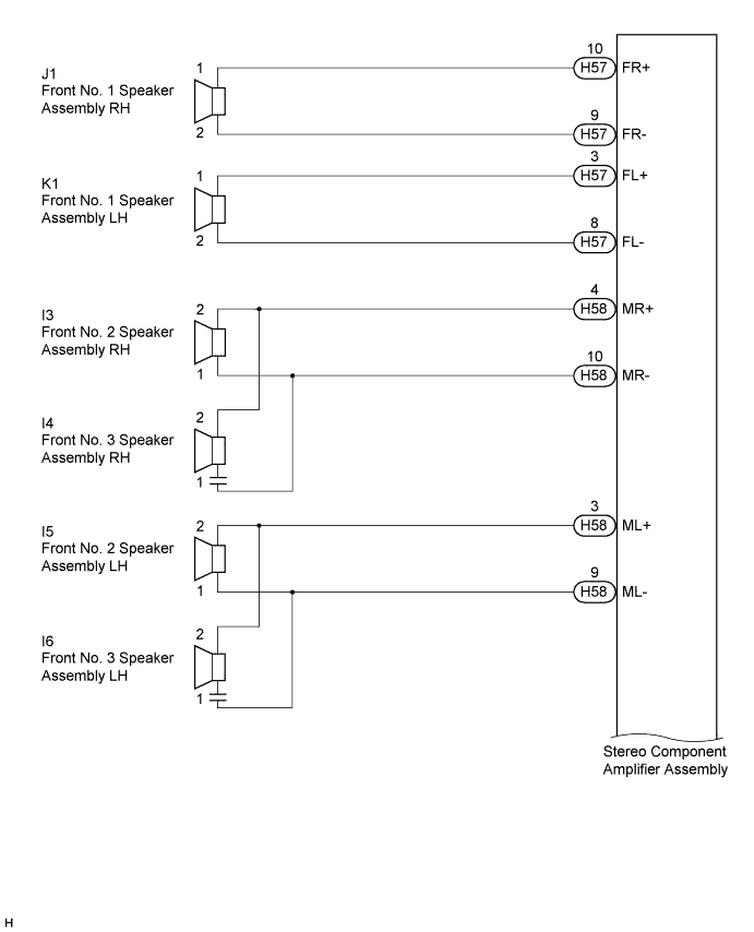
| for 10 Speakers |
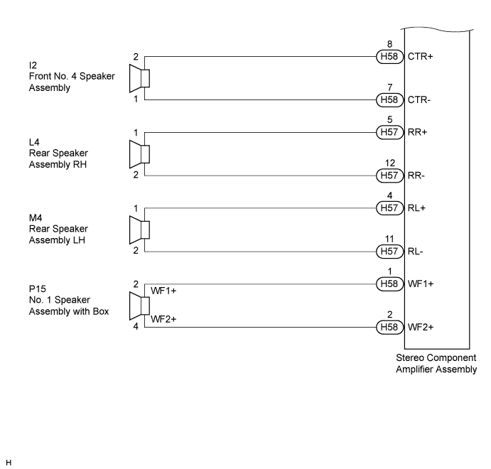
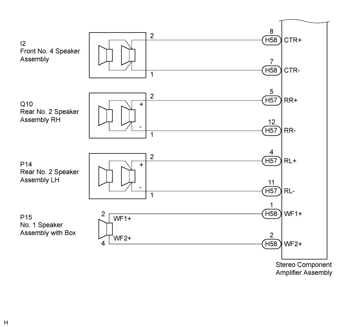
| for 13 Speakers |
| 1.CONFIRM MODEL |
Choose the model to be inspected.
| Model | Proceed to |
| for 10 Speakers | A |
| for 13 Speakers | B |
|
| ||||
| A | |
 |
| 2.CHECK HARNESS AND CONNECTOR |
Disconnect the connectors from the stereo component amplifier assembly and speakers.
Measure the resistance between the front No. 1 speaker assembly RH and the stereo component amplifier assembly to check for an open circuit in the wire harness.
| Tester Connection | Condition | Specified Condition |
| H57-10 (FR+) - J1-1 | Always | Below 1 Ω |
| H57-9 (FR-) - J1-2 | Always | Below 1 Ω |
Measure the resistance between the front No. 1 speaker assembly LH and the stereo component amplifier assembly to check for an open circuit in the wire harness.
| Tester Connection | Condition | Specified Condition |
| H57-3 (FL+) - K1-1 | Always | Below 1 Ω |
| H57-8 (FL-) - K1-2 | Always | Below 1 Ω |
Measure the resistance between the front No. 2 speaker assembly RH and the stereo component amplifier assembly to check for an open circuit in the wire harness.
| Tester Connection | Condition | Specified Condition |
| H58-4 (MR+) - I3-2 | Always | Below 1 Ω |
| H58-10 (MR-) - I3-1 | Always | Below 1 Ω |
Measure the resistance between the front No. 2 speaker assembly LH and the stereo component amplifier assembly to check for an open circuit in the wire harness.
| Tester Connection | Condition | Specified Condition |
| H58-3 (ML+) - I5-2 | Always | Below 1 Ω |
| H58-9 (ML-) - I5-1 | Always | Below 1 Ω |
Measure the resistance between the front No. 3 speaker assembly RH and the stereo component amplifier assembly to check for an open circuit in the wire harness.
| Tester Connection | Condition | Specified Condition |
| H58-4 (MR+) - I4-2 | Always | Below 1 Ω |
| H58-10 (MR-) - I4-1 | Always | Below 1 Ω |
Measure the resistance between the front No. 3 speaker assembly LH and the stereo component amplifier assembly to check for an open circuit in the wire harness.
| Tester Connection | Condition | Specified Condition |
| H58-3 (ML+) - I6-2 | Always | Below 1 Ω |
| H58-9 (ML-) - I6-1 | Always | Below 1 Ω |
Measure the resistance between the front No. 4 speaker assembly and the stereo component amplifier assembly to check for an open circuit in the wire harness.
| Tester Connection | Condition | Specified Condition |
| H58-8 (CTR+) - I2-2 | Always | Below 1 Ω |
| H58-7 (CTR-) - I2-1 | Always | Below 1 Ω |
Measure the resistance between the rear speaker assembly RH and the stereo component amplifier assembly to check for an open circuit in the wire harness.
| Tester Connection | Condition | Specified Condition |
| H57-5 (RR+) - L4-1 | Always | Below 1 Ω |
| H57-12 (RR-) - L4-2 | Always | Below 1 Ω |
Measure the resistance between the rear speaker assembly LH and the stereo component amplifier assembly to check for an open circuit in the wire harness.
| Tester Connection | Condition | Specified Condition |
| H57-4 (RL+) - M4-1 | Always | Below 1 Ω |
| H57-11 (RL-) - M4-2 | Always | Below 1 Ω |
Measure the resistance between the No. 1 speaker assembly with box and the stereo component amplifier assembly to check for an open circuit in the wire harness.
| Tester Connection | Condition | Specified Condition |
| H58-1 (WF1+) - P15-2 (WF1+) | Always | Below 1 Ω |
| H58-2 (WF2+) - P15-4 (WF2+) | Always | Below 1 Ω |
Measure the resistance between the stereo component amplifier assembly and body ground to check for a short circuit in the wire harness.
| Tester Connection | Condition | Specified Condition |
| H57-10 (FR+) - Body ground | Always | 10 kΩ or higher |
| H57-9 (FR-) - Body ground | Always | 10 kΩ or higher |
| H57-3 (FL+) - Body ground | Always | 10 kΩ or higher |
| H57-8 (FL-) - Body ground | Always | 10 kΩ or higher |
| H57-5 (RR+) - Body ground | Always | 10 kΩ or higher |
| H57-12 (RR-) - Body ground | Always | 10 kΩ or higher |
| H57-4 (RL+) - Body ground | Always | 10 kΩ or higher |
| H57-11 (RL-) - Body ground | Always | 10 kΩ or higher |
| H58-4 (MR+) - Body ground | Always | 10 kΩ or higher |
| H58-10 (MR-) - Body ground | Always | 10 kΩ or higher |
| H58-3 (ML+) - Body ground | Always | 10 kΩ or higher |
| H58-9 (ML-) - Body ground | Always | 10 kΩ or higher |
| H58-8 (CTR+) - Body ground | Always | 10 kΩ or higher |
| H58-7 (CTR-) - Body ground | Always | 10 kΩ or higher |
| H58-1 (WF1+) - Body ground | Always | 10 kΩ or higher |
| H58-2 (WF2+) - Body ground | Always | 10 kΩ or higher |
Proceed to the next step based on the inspection result.
| Condition | Proceed to |
| NG | A |
| OK | B |
|
| ||||
| A | ||
 | ||
| ||
| 3.CHECK HARNESS AND CONNECTOR |
Disconnect the connectors from the stereo component amplifier assembly and speakers.
Measure the resistance between the front No. 1 speaker assembly RH and the stereo component amplifier assembly to check for an open circuit in the wire harness.
| Tester Connection | Condition | Specified Condition |
| H57-10 (FR+) - J1-1 | Always | Below 1 Ω |
| H57-9 (FR-) - J1-2 | Always | Below 1 Ω |
Measure the resistance between the front No. 1 speaker assembly LH and the stereo component amplifier assembly to check for an open circuit in the wire harness.
| Tester Connection | Condition | Specified Condition |
| H57-3 (FL+) - K1-1 | Always | Below 1 Ω |
| H57-8 (FL-) - K1-2 | Always | Below 1 Ω |
Measure the resistance between the front No. 2 speaker assembly RH and the stereo component amplifier assembly to check for an open circuit in the wire harness.
| Tester Connection | Condition | Specified Condition |
| H58-4 (MR+) - I3-2 | Always | Below 1 Ω |
| H58-10 (MR-) - I3-1 | Always | Below 1 Ω |
Measure the resistance between the front No. 2 speaker assembly LH and the stereo component amplifier assembly to check for an open circuit in the wire harness.
| Tester Connection | Condition | Specified Condition |
| H58-3 (ML+) - I5-2 | Always | Below 1 Ω |
| H58-9 (ML-) - I5-1 | Always | Below 1 Ω |
Measure the resistance between the front No. 3 speaker assembly RH and the stereo component amplifier assembly to check for an open circuit in the wire harness.
| Tester Connection | Condition | Specified Condition |
| H58-4 (MR+) - I4-2 | Always | Below 1 Ω |
| H58-10 (MR-) - I4-1 | Always | Below 1 Ω |
Measure the resistance between the front No. 3 speaker assembly LH and the stereo component amplifier assembly to check for an open circuit in the wire harness.
| Tester Connection | Condition | Specified Condition |
| H58-3 (ML+) - I6-2 | Always | Below 1 Ω |
| H58-9 (ML-) - I6-1 | Always | Below 1 Ω |
Measure the resistance between the front No. 4 speaker assembly and the stereo component amplifier assembly to check for an open circuit in the wire harness.
| Tester Connection | Condition | Specified Condition |
| H58-8 (CTR+) - I2-2 | Always | Below 1 Ω |
| H58-7 (CTR-) - I2-1 | Always | Below 1 Ω |
Measure the resistance between the rear No. 2 speaker assembly RH and the stereo component amplifier assembly to check for an open circuit in the wire harness.
| Tester Connection | Condition | Specified Condition |
| H57-5 (RR+) - Q10-2 (+) | Always | Below 1 Ω |
| H57-12 (RR-) - Q10-1 (-) | Always | Below 1 Ω |
Measure the resistance between the rear No. 2 speaker assembly LH and the stereo component amplifier assembly to check for an open circuit in the wire harness.
| Tester Connection | Condition | Specified Condition |
| H57-4 (RL+) - P14-2 (+) | Always | Below 1 Ω |
| H57-11 (RL-) - P14-1 (-) | Always | Below 1 Ω |
Measure the resistance between the No. 1 speaker assembly with box and the stereo component amplifier assembly to check for an open circuit in the wire harness.
| Tester Connection | Condition | Specified Condition |
| H58-1 (WF1+) - P15-2 (WF1+) | Always | Below 1 Ω |
| H58-2 (WF2+) - P15-4 (WF2+) | Always | Below 1 Ω |
Measure the resistance between the stereo component amplifier assembly and body ground to check for a short circuit in the wire harness.
| Tester Connection | Condition | Specified Condition |
| H57-10 (FR+) - Body ground | Always | 10 kΩ or higher |
| H57-9 (FR-) - Body ground | Always | 10 kΩ or higher |
| H57-3 (FL+) - Body ground | Always | 10 kΩ or higher |
| H57-8 (FL-) - Body ground | Always | 10 kΩ or higher |
| H57-5 (RR+) - Body ground | Always | 10 kΩ or higher |
| H57-12 (RR-) - Body ground | Always | 10 kΩ or higher |
| H57-4 (RL+) - Body ground | Always | 10 kΩ or higher |
| H57-11 (RL-) - Body ground | Always | 10 kΩ or higher |
| H58-4 (MR+) - Body ground | Always | 10 kΩ or higher |
| H58-10 (MR-) - Body ground | Always | 10 kΩ or higher |
| H58-3 (ML+) - Body ground | Always | 10 kΩ or higher |
| H58-9 (ML-) - Body ground | Always | 10 kΩ or higher |
| H58-8 (CTR+) - Body ground | Always | 10 kΩ or higher |
| H58-7 (CTR-) - Body ground | Always | 10 kΩ or higher |
| H58-1 (WF1+) - Body ground | Always | 10 kΩ or higher |
| H58-2 (WF2+) - Body ground | Always | 10 kΩ or higher |
|
| ||||
| OK | |
|
| 4.INSPECT FRONT NO. 1 SPEAKER ASSEMBLY |
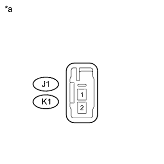 |
Resistance check
Measure the resistance according to the value(s) in the table below.
| Tester Connection | Condition | Specified Condition |
| J1-1 - J1-2 | Always | 3.2 to 4.8 Ω |
| K1-1 - K1-2 | Always | 3.2 to 4.8 Ω |
| Tester Connection | Condition | Specified Condition |
| J1-1 - J1-2 | Always | 5 to 7 Ω |
| K1-1 - K1-2 | Always | 5 to 7 Ω |
| *a | Component without harness connected (Front No. 1 Speaker Assembly) |
|
| ||||
| OK | |
|
| 5.INSPECT FRONT NO. 2 SPEAKER ASSEMBLY |
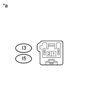 |
Resistance check
Measure the resistance according to the value(s) in the table below.
| Tester Connection | Condition | Specified Condition |
| I3-2 - I3-1 | Always | 3.2 to 4.8 Ω |
| I5-2 - I5-1 | Always | 3.2 to 4.8 Ω |
| Tester Connection | Condition | Specified Condition |
| I3-2 - I3-1 | Always | 4.6 to 7 Ω |
| I5-2 - I5-1 | Always | 4.6 to 7 Ω |
| *a | Component without harness connected (Front No. 2 Speaker Assembly) |
|
| ||||
| OK | |
|
| 6.INSPECT FRONT NO. 3 SPEAKER ASSEMBLY |
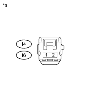 |
Resistance check
Measure the resistance according to the value(s) in the table below.
| Tester Connection | Condition | Specified Condition |
| I4-2 - I4-1 | Always | 10 kΩ or higher |
| I6-2 - I6-1 | Always | 10 kΩ or higher |
| *a | Component without harness connected (Front No. 3 Speaker Assembly) |
|
| ||||
| OK | |
|
| 7.REPLACE FRONT NO. 3 SPEAKER ASSEMBLY |
Check that the malfunction disappears when a known good speaker is installed (Click here).
|
| ||||
| OK | ||
| ||
| ||
| 8.INSPECT FRONT NO. 4 SPEAKER ASSEMBLY |
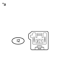 |
Resistance check
Measure the resistance according to the value(s) in the table below.
| Tester Connection | Condition | Specified Condition |
| I2-1 - I2-2 | Always | 3.2 to 4.8 Ω |
| Tester Connection | Condition | Specified Condition |
| I2-1 - I2-2 | Always | 4.6 to 7 Ω |
| *a | Component without harness connected (Front No. 4 Speaker Assembly) |
|
| ||||
| OK | |
|
| 9.CONFIRM MODEL |
Choose the model to be inspected.
| Model | Proceed to |
| for 10 Speakers | A |
| for 13 Speakers | B |
|
| ||||
| A | |
|
| 10.INSPECT REAR SPEAKER ASSEMBLY |
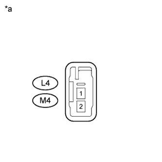 |
Resistance check
Measure the resistance according to the value(s) in the table below.
| Tester Connection | Condition | Specified Condition |
| L4-1 - L4-2 | Always | 3.2 to 4.8 Ω |
| M4-1 - M4-2 | Always | 3.2 to 4.8 Ω |
| *a | Component without harness connected (Rear Speaker Assembly) |
Proceed to the next step based on the inspection result.
| Condition | Proceed to |
| NG | A |
| OK | B |
|
| ||||
| A | ||
| ||
| ||
| 11.INSPECT REAR NO. 2 SPEAKER ASSEMBLY |
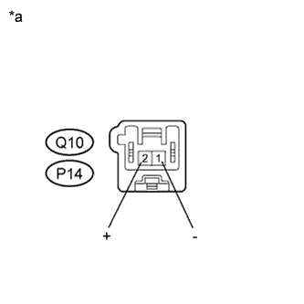 |
Resistance check
Measure the resistance according to the value(s) in the table below.
| Tester Connection | Condition | Specified Condition |
| Q10-1 (-) - Q10-2 (+) | Always | 4.6 to 7 Ω |
| P14-1 (-) - P14-2 (+) | Always | 4.6 to 7 Ω |
| *a | Component without harness connected (Rear No. 2 Speaker Assembly) |
|
| ||||
| OK | |
|
| 12.INSPECT NO. 1 SPEAKER ASSEMBLY WITH BOX |
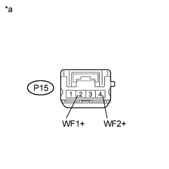 |
Resistance check
Measure the resistance according to the value(s) in the table below.
| Tester Connection | Condition | Specified Condition |
| P15-2 (WF1+) - P15-4 (WF2+) | Always | 1.6 to 2.4 Ω |
| Tester Connection | Condition | Specified Condition |
| P15-2 (WF1+) - P15-4 (WF2+) | Always | 11.6 to 12.4 Ω |
| *a | Component without harness connected (No. 1 Speaker Assembly with Box) |
|
| ||||
| OK | ||
| ||
| ||

