Home Engine / Hybrid System HYBRID / BATTERY CONTROL COMBINATION SWITCH

COMBINATION SWITCH > INSPECTION

for Preparation Click here


1. INSPECT COMBINATION SWITCH ASSEMBLY


  1. Inspect EV switch


      A237666E04
    1. Measure the resistance according to the value(s) in the table below.

      Standard Resistance:
      Tester Connection
      Condition
      Specified Condition
      H72-3 (S) - H72-14 (E)
      EV switch being pushed and held
      Below 1 Ω
      EV switch not pushed
      10 kΩ or higher

      Text in Illustration 
      *a
      Component without Harness Connected
      (Combination Switch Assembly)
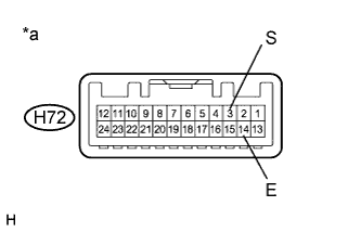
      If the result is not as specified, replace the combination switch assembly.


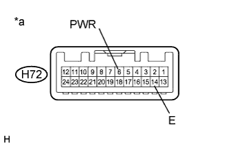
  1. Inspect SPORT mode switch


      A237666E09
    1. Measure the resistance according to the value(s) in the table below.

      Standard Resistance:
      Tester Connection
      Condition
      Specified Condition
      H72-6 (PWR) - H72-14 (E)
      Mode switch being turned and held at SPORT position
      Below 1 Ω
      Mode switch not turned
      10 kΩ or higher

      Text in Illustration 
      *a
      Component without Harness Connected
      (Combination Switch Assembly)
      If the result is not as specified, replace the combination switch assembly.


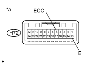
  1. Inspect ECO mode switch


      A237666E10
    1. Measure the resistance according to the value(s) in the table below.

      Standard Resistance:
      Tester Connection
      Condition
      Specified Condition
      H72-5 (ECO) - H72-13 (E)
      Mode switch being turned and held at ECO position
      Below 1 Ω
      Mode switch not turned
      10 kΩ or higher

      Text in Illustration 
      *a
      Component without Harness Connected
      (Combination Switch Assembly)
      If the result is not as specified, replace the combination switch assembly.


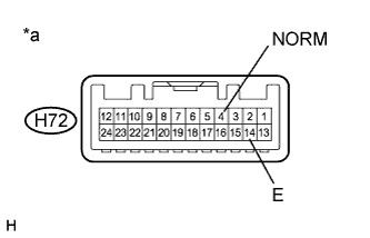
  1. Inspect NORMAL mode switch


      A237666E11
    1. Measure the resistance according to the value(s) in the table below.

      Standard Resistance:
      Tester Connection
      Condition
      Specified Condition
      H72-4 (NORM) - H72-14 (E)
      Mode switch being pushed and held at NORMAL position
      Below 1 Ω
      Mode switch not pushed
      10 kΩ or higher

      Text in Illustration 
      *a
      Component without Harness Connected
      (Combination Switch Assembly)
      If the result is not as specified, replace the combination switch assembly.


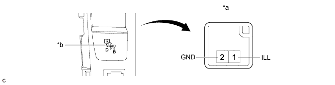
  1. Inspect illumination


    A248475E01


    Text in Illustration 
    *a
    Component without Harness Connected
    (Combination Switch Assembly)
    *b
    Integration Control and Panel Assembly Illumination

    1. Apply battery voltage between the terminals of the switch, and check the illumination condition of the combination switch assembly.

      Standard:
      Measurement Condition
      Specified Condition
      Auxiliary battery positive (+) →Terminal E115-1 (ILL+)
      Auxiliary battery negative (-) →Terminal E115-2 (ILL-)
      illuminates

      If the result is not as specified, replace the integration control and panel assembly.


2. INSPECT POSITION INDICATOR HOUSING ASSEMBLY


  1. Inspect illumination


    A248477E01


    Text in Illustration 
    *a
    Component without Harness Connected
    (Position Indicator Housing Assembly)
    *b
    Position indicator housing assembly illumination

    1. Apply battery voltage between the terminals of the switch, and check the illumination condition of the combination switch assembly.

      Standard:
      Measurement Condition
      Specified Condition
      Auxiliary battery positive (+) →Terminal E115-1 (ILL+)
      Auxiliary battery negative (-) →Terminal E115-2 (ILL-)
      illuminates

      If the result is not as specified, replace the combination switch assembly.


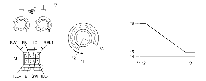
3. INSPECT SEAT HEATER SWITCH


  1. Check operation of the seat heater switch.


    B270921E01


    Text in Illustration 
    *1
    0°(Off)
    *2
    27°(On (Min.))
    *3
    300° (On(MAX.))
    *4
    0 kΩ
    *5
    0.28 to 0.42 kΩ
    *6
    2.72 to 4.08 kΩ
    *7
    Seat Heater Switch Indicator
    -
    -
    *a
    Component without harness connected
    (Seat Heater Switch)
    -
    -

    1. Measure the resistance according to the value(s) in the table below.

      Standard Resistance:
      LH Side 
      Tester Connection
      Switch Condition
      Specified Condition
      3 (RV) - 4 (SW)
      Off
      0.28 to 0.42 kΩ
      3 (RV) - 4 (SW)
      On (Min.)
      0.28 to 0.42 kΩ
      3 (RV) - 4 (SW)
      On (Max.)
      2.72 to 4.08 kΩ
      RH Side 
      Tester Connection
      Switch Condition
      Specified Condition
      1 (REL1) - 6 (SW)
      Off
      0.28 to 0.42 kΩ
      1 (REL1) - 6 (SW)
      On (Min.)
      0.28 to 0.42 kΩ
      1 (REL1) - 6 (SW)
      On (Max.)
      2.72 to 4.08 kΩ

      If the result is not as specified, replace the seat heater switch.

  1. Check operation of the seat heater switch indicator.

    1. Apply auxiliary battery voltage and check operation of the switch as shown in the table below.

      Standard:
      Measurement Condition
      Switch Condition
      Specified Condition
      Auxiliary battery positive (+) → Terminal 2 (IG)
      Auxiliary battery negative (-) → Terminal 7 (E)
      Seat heater switch on
      Indicator comes on

      If the result is not as specified, replace the seat heater switch.

  1. Check the illumination of the seat heater switch.

    1. Apply auxiliary battery voltage and check operation of the switch as shown in the table below.

      Standard:
      Measurement Condition
      Specified Condition
      Auxiliary battery positive (+) → Terminal 8 (ILL+)
      Auxiliary battery negative (-) → Terminal 5 (ILL-)
      Illumination comes on