 |
Remove the clip.
COMBINATION SWITCH > REMOVAL |
| 1. PRECAUTION |
| 2. REMOVE REAR NO. 2 FLOOR BOARD |
Remove the rear No. 2 floor board.
| 3. REMOVE REAR DECK FLOOR BOX |
Remove the rear deck floor box.
| 4. REMOVE REAR NO. 3 FLOOR BOARD |
Remove the rear No. 3 floor board.
| 5. REMOVE DECK FLOOR BOX RH |
|
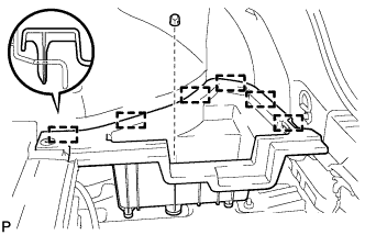
Remove the clip.
Disengage the 6 guides and remove the deck floor box RH.
| 6. REMOVE REAR FLOOR BOARD UPPER NO. 3 PLATE |
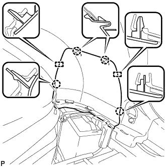 |
Disengage the 4 claws and 2 guides, and remove the rear floor board upper No. 3 plate.
| 7. DISCONNECT CABLE FROM NEGATIVE AUXILIARY BATTERY TERMINAL |
| 8. REMOVE LOWER CENTER INSTRUMENT PANEL FINISH PANEL |
Open the glove compartment door.
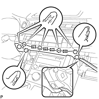 |
Using a moulding remover, disengage the 7 claws and 4 guides, and remove the lower center instrument panel finish panel as shown in the illustration.
| 9. REMOVE UPPER NO. 1 CONSOLE PANEL GARNISH |
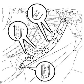 |
Disengage the 4 claws, clip and 3 guides, and remove the upper No. 1 console panel garnish.
| 10. REMOVE UPPER NO. 2 CONSOLE PANEL GARNISH |
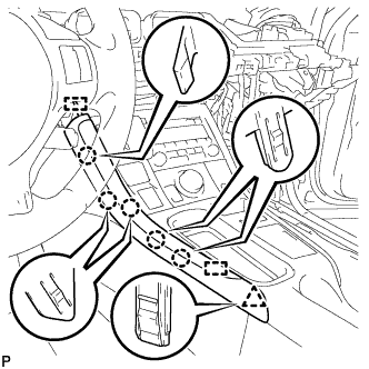 |
Disengage the 5 claws, clip and 2 guides, and remove the upper No. 2 console panel garnish.
| 11. REMOVE UPPER CONSOLE PANEL SUB-ASSEMBLY |
Open the console compartment door.
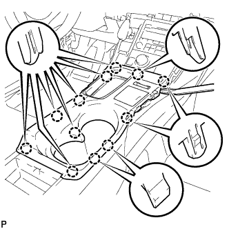 |
Using a moulding remover, disengage the 12 claws.
Disengage the clamp.
Disconnect each connector and remove the upper console panel sub-assembly.
| 12. REMOVE SHIFT LEVER KNOB SUB-ASSEMBLY |
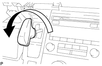 |
Turn the shift lever knob counterclockwise and remove the shift lever knob sub-assembly.
| 13. REMOVE COMBINATION SWITCH ASSEMBLY |
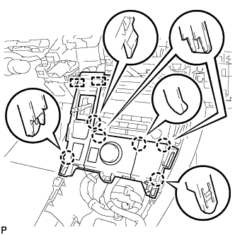 |
Disengage the 6 claws and 2 guides.
Disengage the clamp.
Disconnect each connector and remove the combination switch assembly.
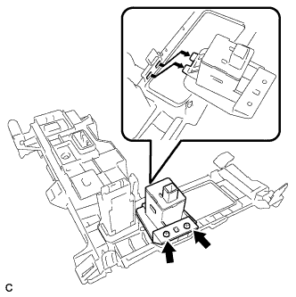 |
Remove the 2 screws and position indicator housing assembly from the combination switch assembly.
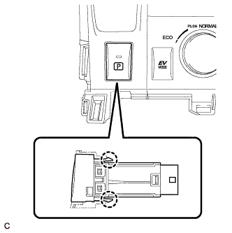 |
Disengage the 2 claws and remove the transmission shift main switch.