Home Vehicle Interior HEATING / AIR CONDITIONING HUMIDITY SENSOR

HUMIDITY SENSOR > INSPECTION

for Preparation Click here


1. INSPECT AIR CONDITIONING THERMISTOR ASSEMBLY


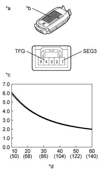
  1. for Glass temperature sensor


      E208908E11
    1. Remove the air conditioning thermistor assembly (glass temperature sensor).

    2. Measure the resistance according to the value(s) in the table below.

      Standard Resistance:
      Tester Connection
      Condition
      Specified Condition
      1 (SEG3) - 4 (TFG)
      10°C (50°F)
      5.92 to 6.09 kΩ
      1 (SEG3) - 4 (TFG)
      15°C (59°F)
      4.94 to 5.07 kΩ
      1 (SEG3) - 4 (TFG)
      20°C (68°F)
      4.20 to 4.29 kΩ
      1 (SEG3) - 4 (TFG)
      25°C (77°F)
      3.64 to 3.70 kΩ
      1 (SEG3) - 4 (TFG)
      30°C (86°F)
      3.19 to 3.26 kΩ
      1 (SEG3) - 4 (TFG)
      35°C (95°F)
      2.85 to 2.91 kΩ
      1 (SEG3) - 4 (TFG)
      40°C (104°F)
      2.58 to 2.64 kΩ
      1 (SEG3) - 4 (TFG)
      45°C (113°F)
      2.37 to 2.43 kΩ
      1 (SEG3) - 4 (TFG)
      50°C (122°F)
      2.21 to 2.26 kΩ
      1 (SEG3) - 4 (TFG)
      55°C (131°F)
      2.07 to 2.12 kΩ
      1 (SEG3) - 4 (TFG)
      60°C (140°F)
      1.97 to 2.01 kΩ

      NOTICE:
      1. Hold the sensor only by its connector. Touching the sensor may change the resistance value.
      2. When measuring, the sensor temperature must be the same as the ambient temperature.

      HINT:
      As the temperature increases, the resistance decreases (see the graph).

      If the resistance is not as specified, replace the air conditioning thermistor assembly (glass temperature sensor).
      Text in Illustration 
      *a
      Component without harness connected
      (Air Conditioning Thermistor Assembly (Glass Temperature Sensor))
      *b
      Heat Conduction Sheet Part
      *c
      Resistance (kΩ)
      *d
      Temperature (°C (°F))


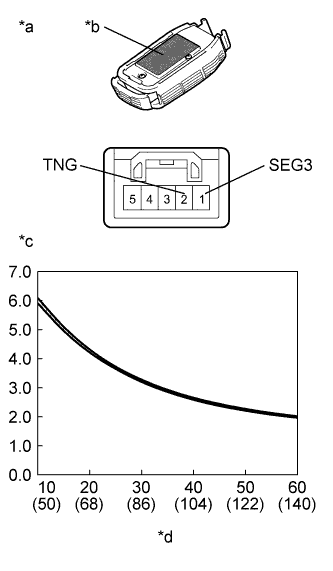
  1. for Glass surroundings temperature sensor


      E208908E09
    1. Remove the air conditioning thermistor assembly (glass surroundings temperature sensor).

    2. Measure the resistance according to the value(s) in the table below.

      Standard Resistance:
      Tester Connection
      Condition
      Specified Condition
      1 (SEG3) - 2 (TNG)
      10°C (50°F)
      5.92 to 6.09 kΩ
      1 (SEG3) - 2 (TNG)
      15°C (59°F)
      4.94 to 5.07 kΩ
      1 (SEG3) - 2 (TNG)
      20°C (68°F)
      4.20 to 4.29 kΩ
      1 (SEG3) - 2 (TNG)
      25°C (77°F)
      3.64 to 3.70 kΩ
      1 (SEG3) - 2 (TNG)
      30°C (86°F)
      3.19 to 3.26 kΩ
      1 (SEG3) - 2 (TNG)
      35°C (95°F)
      2.85 to 2.91 kΩ
      1 (SEG3) - 2 (TNG)
      40°C (104°F)
      2.58 to 2.64 kΩ
      1 (SEG3) - 2 (TNG)
      45°C (113°F)
      2.37 to 2.43 kΩ
      1 (SEG3) - 2 (TNG)
      50°C (122°F)
      2.21 to 2.26 kΩ
      1 (SEG3) - 2 (TNG)
      55°C (131°F)
      2.07 to 2.12 kΩ
      1 (SEG3) - 2 (TNG)
      60°C (140°F)
      1.97 to 2.01 kΩ

      NOTICE:
      1. Hold the sensor only by its connector. Touching the sensor may change the resistance value.
      2. When measuring, the sensor temperature must be the same as the ambient temperature.

      HINT:
      As the temperature increases, the resistance decreases (see the graph).

      If the resistance is not as specified, replace the air conditioning thermistor assembly (glass surroundings temperature sensor).
      Text in Illustration 
      *a
      Component without harness connected
      (Air Conditioning Thermistor Assembly (Glass Surroundings Temperature Sensor))
      *b
      Heat Conduction Sheet Part
      *c
      Resistance (kΩ)
      *d
      Temperature (°C (°F))


  1. for Glass humidity sensor


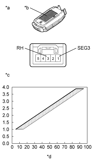
      E208909E05
    1. Remove the air conditioning thermistor assembly (glass humidity sensor) with the connector still connected.

    2. Measure the voltage according to the value(s) in the table below.

      Standard Voltage:
      Tester Connection
      Condition
      Specified Condition
      1 (SEG3) - 3 (RH)
      Power switch on (IG)
      Humidity is 5 to 15 %
      Approximately 1.01 V
      1 (SEG3) - 3 (RH)
      Power switch on (IG)
      Humidity is 15 to 25 %
      Approximately 1.37 V
      1 (SEG3) - 3 (RH)
      Power switch on (IG)
      Humidity is 25 to 35 %
      Approximately 1.73 V
      1 (SEG3) - 3 (RH)
      Power switch on (IG)
      Humidity is 35 to 45 %
      Approximately 2.09 V
      1 (SEG3) - 3 (RH)
      Power switch on (IG)
      Humidity is 45 to 55 %
      Approximately 2.45 V
      1 (SEG3) - 3 (RH)
      Power switch on (IG)
      Humidity is 55 to 65 %
      Approximately 2.81 V
      1 (SEG3) - 3 (RH)
      Power switch on (IG)
      Humidity is 65 to 75 %
      Approximately 3.17 V
      1 (SEG3) - 3 (RH)
      Power switch on (IG)
      Humidity is 75 to 85 %
      Approximately 3.53 V
      1 (SEG3) - 3 (RH)
      Power switch on (IG)
      Humidity is 85 to 95 %
      Approximately 3.89 V

      NOTICE:
      1. Do not touch the sensor as body heat will affect the inspection results. When performing the inspection, hold the sensor by its connector.
      2. Allow the sensor to acclimate to the ambient temperature and humidity before performing the inspection.
      3. The specified voltages in the table above are based on inspections performed when the ambient temperature is 25°C (77°F).

      HINT:
      As the humidity increases, the voltage increases (see the graph).
      If the voltage is not as specified, replace the air conditioning thermistor assembly (glass humidity sensor).

      Text in Illustration 
      *a
      Component with harness connected
      (Air Conditioning Thermistor Assembly (Glass Humidity Sensor))
      *b
      Heat Conduction Sheet Part
      *c
      Voltage (V)
      *d
      Relative Humidity (%)