Home Vehicle Interior THEFT DETERRENT / KEYLESS ENTRY ENGINE IMMOBILISER SYSTEM

DTC    B2779    Engine Starter Communication Malfunction

for Preparation Click here


DESCRIPTION

If communication between the remote start ECU and certification ECU (smart key ECU assembly) cannot be performed even if a remote start operation is performed to try changing the power source mode to on (IG) or start the hybrid control system, this DTC is stored.
When the remote start ECU does not respond to the certification ECU (smart key ECU assembly), this DTC is stored. When communication with the remote start ECU is established and a remote start operation is performed, this DTC is cleared.

DTC Code
DTC Detection Condition
Trouble Area
DTC Output Confirmation Operation
B2779
One of the following conditions is met (1 trip detection logic*):
  1. A remote start communication error occurs.
  2. Response is not possible.
  3. Registration has not been performed.
  1. Remote start ECU
  2. Wire harness or connector
  3. Main body ECU (multiplex network body ECU)
  4. Certification ECU (smart key ECU assembly)
A remote start operation is performed.
  1. *: Only output while a malfunction is present.

Vehicle Condition and Fail-safe Operation when Malfunction Detected 
Vehicle Condition when Malfunction Detected
Fail-safe Operation when Malfunction Detected
Hybrid control system does not start with remote start operation
Hybrid control system cannot be started by remote start operation only

Related Data List and Active Test 
DTC Code
Data List and Active Test
B2779
  1. Wireless Starter Com ID
  2. Wireless C Code

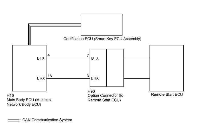
WIRING DIAGRAM


B270937E01


INSPECTION PROCEDURE

NOTICE:
  1. Inspect the fuses for circuits related to this system before performing the following inspection procedure.
  2. Before performing the inspection, check that DTC U0142 is not output.
  3. Before replacing the certification ECU (smart key ECU assembly), refer to the Service Bulletin.
  4. After performing repair, perform the operation that fulfills the DTC output confirmation operation, and then confirm that no DTCs are output again.

HINT:
In this repair manual, only the terminal numbers used for inspection between the main body ECU (multiplex network body ECU) and option connector are listed.

1.READ VALUE USING INTELLIGENT TESTER
  1. Turn the power switch off.

  1. Connect the intelligent tester to the DLC3.

  1. Turn the power switch on (IG).

  1. Turn the intelligent tester on.

  1. Enter the following menus: Body / Entry&Start / Data List.

  1. According to the display on the intelligent tester, read the Data List.

    Entry&Start (Certification ECU (Smart Key ECU Assembly)) 
    Tester Display
    Measurement Item/Range
    Normal Condition
    Diagnostic Note
    Wireless C Code
    Registration status between remote start ECU and certification ECU (smart key ECU assembly)/No Regd or Regd
    No Regd: ID not registered between remote start ECU and certification ECU (smart key ECU assembly)
    Regd: ID registered between remote start ECU and certification ECU (smart key ECU assembly)
    Problems may be caused by the following:
    1. Remote start ECU registration has not been performed.
    2. Malfunctions in the certification ECU (smart key ECU assembly) or remote start ECU.

    OK:
    "Regd" appears on the screen.

    Result 
    Result
    Proceed to
    "No Regd" appears on the screen
    A
    "Regd" appears on the screen
    B


B
Go to step 4
A


2.REGISTER REMOTE START ID
  1. Register the remote start ID.


NEXT


3.CHECK REMOTE START
  1. Check that the hybrid control system can be started using remote start operation.

    OK:
    Hybrid control system can be started using remote start operation.


NG
Go to step 4
OK

END (REMOTE START ID WAS NOT REGISTERED CORRECTLY) 

4.CHECK HARNESS AND CONNECTOR (MAIN BODY ECU - OPTION CONNECTOR)

HINT:
In this repair manual, only the terminal numbers used for inspection between the main body ECU and option connector are listed.

  1. Disconnect the H16 main body ECU (multiplex network body ECU) connector.

  1. Disconnect the H90 option connector.

  1. Measure the resistance according to the value(s) in the table below.

    Standard Resistance:
    Tester Connection
    Condition
    Specified Condition
    H16-4 (BTX) - H90-7 (BTX)
    Always
    Below 1 Ω
    H16-16 (BRX) - H90-3 (BRX)
    H16-4 (BTX) - Body ground
    Always
    10 kΩ or higher
    H16-16 (BRX) - Body ground


NG
REPAIR OR REPLACE HARNESS OR CONNECTOR
OK


5.REPLACE REMOTE START
  1. Temporarily replace the remote start ECU with a new one.

  1. Register the remote start ID.

  1. Check that the hybrid control system can be started using remote start operation.

    OK:
    Hybrid control system can be started using remote start operation.


NG
Go to step 6
OK

END (REMOTE START ECU WAS DEFECTIVE) 

6.REPLACE MAIN BODY ECU (MULTIPLEX NETWORK BODY ECU)
  1. Temporarily replace the main body ECU (multiplex network body ECU) with a new or known good one (Click here).

  1. Check that the hybrid control system can be started using remote start operation.

    OK:
    Hybrid control system can be started using remote start operation.


NG
REPLACE CERTIFICATION ECU (SMART KEY ECU ASSEMBLY)
OK

END (MAIN BODY ECU (MULTIPLEX NETWORK BODY ECU) WAS DEFECTIVE)