HV BATTERY > CHARGING |
| 1. INSPECT AUXILIARY BATTERY VOLTAGE |
Measure the voltage between the terminals of the auxiliary battery.
Check the charge level of the HV battery.
![]() |
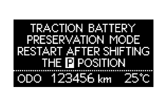
Check whether the HV battery warning message is shown in the multi-information display.
Confirm if the engine starts. If the engine starts, leave it idling with park (P) selected until the engine stops (self charge has completed).
If the engine cannot start, follow the procedure and charge the HV battery.
| 2. PREPARATION FOR HV BATTERY CHARGING |
Disconnect the negative terminal of the auxiliary battery.
Remove the service plug grip (Click here).
Remove the inverter cover assembly LH (w/cover) .
Remove the inverter cover .
Check terminal voltage .
![]() |
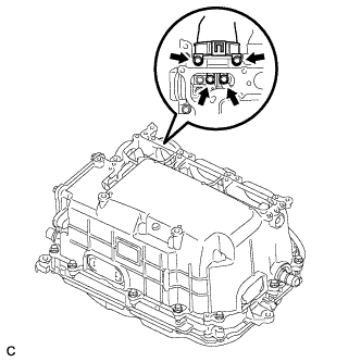
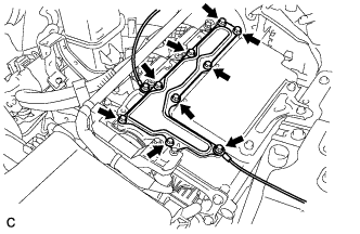
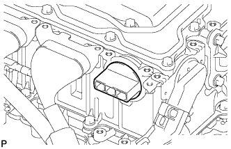
Remove the 4 bolts and disconnect the frame wire.
![]() |
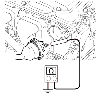
Measure the resistance according to the value(s) in the table below.
| Tester Connection | Condition | Specified Condition |
| Frame wire connector housing - Body ground | Always | Below 1 Ω |
![]() |
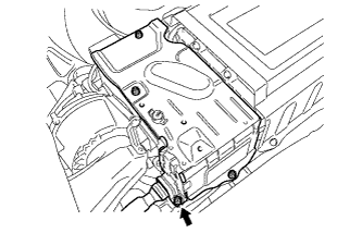
If the result is not as specified, inspect the connection shown in the illustration for proper installation .
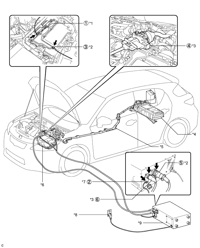
Connect the THS charger in the order shown by the circled numbers in the illustration.

| *1 | EV Bonding Cable (Green Cable) | *2 | Low Voltage Cable |
| *3 | High Voltage Cable | *4 | HV Battery |
| *5 | Frame Wire | *6 | Inverter with Converter Assembly |
| *7 | EV Bonding Cable | *8 | Grounded AC 100 to 240 V Receptacle |
| *9 | THS Charger | - | - |
![]() |
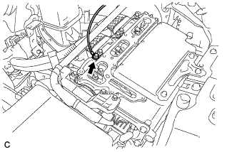
Connect the EV bonding cable to the inverter with converter assembly.
![]() |
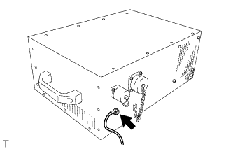
Connect the EV bonding cable to the THS charger.
![]() |
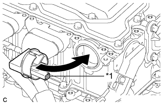
Install the inverter cover to the inverter with converter assembly.
Connect the low voltage cables to the positions shown in the illustration, and then tighten the 9 bolts.
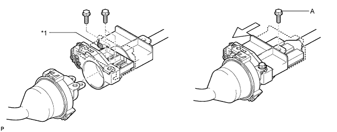
Connect the disconnected frame wire to the high voltage cable with 3 bolts as shown in the illustration.

| *1 | Interlock | - | - |
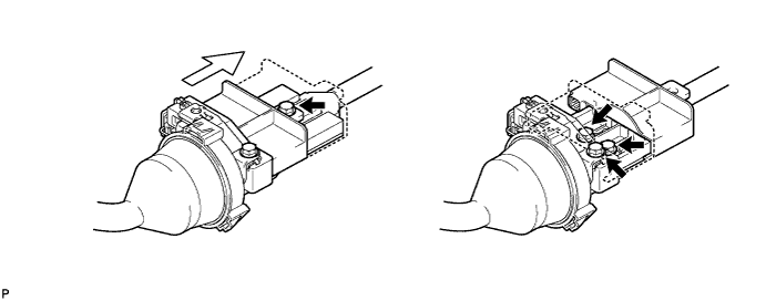
Slide the cover as shown in the illustration and install bolt A.
![]() |
Install the interlock cover over the location where the frame wire is connected.
| *1 | Interlock |
![]() |
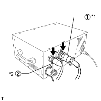
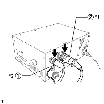
Connect the low voltage cable and high voltage cable to the THS charger in the order shown in the illustration.
| *1 | Low Voltage Cable |
| *2 | High Voltage Cable |
Install the service plug grip (Click here).
Connect the negative auxiliary battery terminal.
Connect the power input plug of the charger to a grounded AC 100 to 240 V receptacle.
| 3. HV BATTERY CHARGING |
Turn the power switch of the vehicle on (IG).
Connect the intelligent tester to the DLC3.
Enter the following menus: Powertrain / Hybrid Control / Active Test / Battery Charge.
| Step | Active Test Battery Charge | THS charger START switch | Data List System Main Relay Status - SMRB | Data List System Main Relay Status - SMRG |
| 1 | OFF | OFF | OFF | OFF |
| 2 | OFF → ON | OFF | OFF → ON | OFF → ON |
| 3 | ON | OFF → ON | ON | ON |
Make sure that the EMERGENCY STOP switch is in the reset condition (the switch is turned clockwise and released).
Make sure that the BREAKER is in the ON position.
![]() |
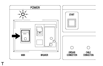
Turn the THS charger MAIN switch on.
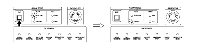
Press the START switch.

Repeat the charge cycle 3 times. When the last cycle has finished, turn the THS charger MAIN switch off.
Turn the power switch off.
Remove the THS charger and install the frame wire.
Disconnect the power inlet plug of the charger from the receptacle.
Disconnect the negative terminal of the auxiliary battery.
Remove the service plug grip (Click here).
![]() |
Disconnect the high voltage cable and low voltage cable from the THS charger in the order shown in the illustration.
| *1 | Low Voltage Cable |
| *2 | High Voltage Cable |
![]() |
Remove the interlock cover from the inverter with converter assembly.
Remove the bolt and slide the cover as shown in the illustration.

Remove the 3 bolts and disconnect the high voltage cable from the frame wire.
![]() |
Remove the 9 bolts, low voltage cable and inverter cover.
![]() |
Disconnect the EV bonding cable from the THS charger.
![]() |
Remove the bolt and disconnect the EV bonding cable from the inverter with converter assembly.
![]() |
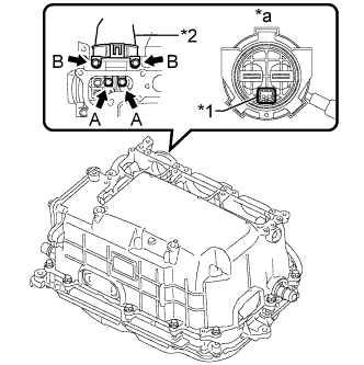
Temporarily install the frame wire (high voltage cables of the hybrid battery) and 4 bolts to the inverter assembly by hand.
| *1 | Interlock |
| *2 | High voltage cables of the hybrid battery |
| *a | Front view of frame wire connector |
Fully tighten the 4 bolts.
Install the inverter cover .
Install the inverter cover assembly LH (w/cover) .
Install the service plug grip (Click here).
Connect the negative terminal of the auxiliary battery.
Check if the engine starts.
Return the vehicle to its original condition.
| 4. CHECK HV BATTERY AFTER HV BATTERY CHARGE |
Check for DTCs.
Perform the self-charging operation.
Start the engine and leave park (P) selected until the engine stops idling.