| NG |  |
| Go to step 4 |
DTC P0AE0-228 Hybrid Battery Negative Contactor Control Circuit High |
| DTC No. | INF Code | DTC Detection Condition | Trouble Area |
| P0AE0 | 228 | Open or +B short in SMR3 (CON3) circuit |
|
| 1.READ VALUE USING INTELLIGENT TESTER (SMRG STATUS) |
Connect the intelligent tester to the DLC3.
Turn the power switch on (IG).
Enter the following menus: Powertrain / Hybrid Control / Data List / SMRG Status.
Read the Data List.
| Tester Connection | Switch Condition | Specified Condition |
| SMRG Status | Power switch on (IG) | OFF |
Turn the power switch off.
|
| ||||
| OK | |
 |
| 2.CHECK CONNECTOR CONNECTION CONDITION (POWER MANAGEMENT CONTROL ECU CONNECTOR) |
Check the connector connections and contact pressure of the relevant terminals for the power management control ECU connectors.
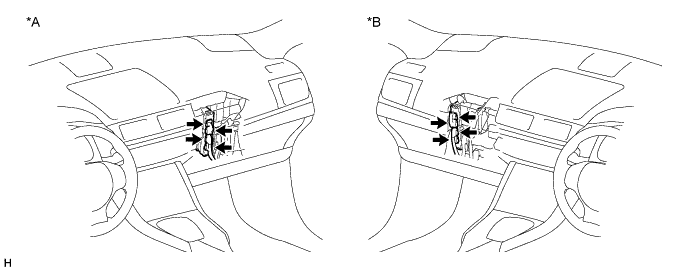
| *A | for LHD | *B | for RHD |
|
| ||||
| OK | |
|
| 3.CHECK CONNECTOR CONNECTION CONDITION (HYBRID BATTERY JUNCTION BLOCK ASSEMBLY CONNECTOR) |
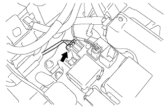 |
Check the condition of the hybrid battery junction block assembly connector.
|
| ||||
| OK | ||
 | ||
| ||
| 4.CHECK HARNESS AND CONNECTOR (SMRG VOLTAGE) |
Turn the power switch on (IG).
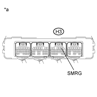 |
Measure the voltage according to the value(s) in the table below.
| Tester Connection | Switch Condition | Specified Condition |
| H3-2 (SMRG) - Body ground | Power switch on (IG) | Below 1 V |
| *a | Component with harness connected (Power Management Control ECU) |
Turn the power switch off.
|
| ||||
| OK | |
|
| 5.CHECK CONNECTOR CONNECTION CONDITION (POWER MANAGEMENT CONTROL ECU CONNECTOR) |
Check the connector connections and contact pressure of the relevant terminals for the power management control ECU connectors.
| *A | for LHD | *B | for RHD |
|
| ||||
| OK | ||
| ||
| ||
| 6.CHECK HARNESS AND CONNECTOR (POWER MANAGEMENT CONTROL ECU - BODY GROUND) |
Disconnect connector H3 from the power management control ECU.
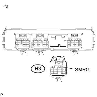 |
Measure the resistance according to the value(s) in the table below.
| Tester Connection | Switch Condition | Specified Condition |
| H3-2 (SMRG) - Body ground | Power switch off | 19.0 to 35.5 Ω |
| *a | Rear view of wire harness connector (to Power Management Control ECU) |
Connect the power management control ECU connector.
|
| ||||
| OK | |
|
| 7.CHECK HARNESS AND CONNECTOR (SHORT TO POWER SUPPLY WIRES) |
Check that the service plug grip is not installed.
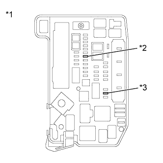 |
Remove the IGCT NO. 2 and AM2 fuses from the engine room junction block assembly.
| *1 | Engine Room Junction Block Assembly |
| *2 | AM2 fuse |
| *3 | IGCT NO. 2 fuse |
Remove the upper hybrid battery cover sub-assembly.
Disconnect connector i3 from the hybrid battery junction block assembly.
Disconnect all the connectors from the power management control ECU.
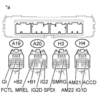 |
Measure the resistance according to the value(s) in the table below.
| Tester Connection | Switch Condition | Specified Condition |
| H3-2 (SMRG) - A19-2 (+B2) | Power switch off | 10 kΩ or higher |
| H3-2 (SMRG) - A20-5 (+B1) | Power switch off | 10 kΩ or higher |
| H3-2 (SMRG) - H3-1 (AM22) | Power switch off | 10 kΩ or higher |
| H3-2 (SMRG) - H4-7 (AM21) | Power switch off | 10 kΩ or higher |
| H3-2 (SMRG) - A20-6 (MREL) | Power switch off | 10 kΩ or higher |
| H3-2 (SMRG) - A20-1 (IG2) | Power switch off | 10 kΩ or higher |
| H3-2 (SMRG) - H4-1 (ACCD) | Power switch off | 10 kΩ or higher |
| H3-2 (SMRG) - H4-2 (IG1D) | Power switch off | 10 kΩ or higher |
| H3-2 (SMRG) - A20-2 (IG2D) | Power switch off | 10 kΩ or higher |
| H3-2 (SMRG) - H3-14 (SPDI) | Power switch off | 10 kΩ or higher |
| H3-2 (SMRG) - A19-16 (GI) | Power switch off | 10 kΩ or higher |
| H3-2 (SMRG) - A19-4 (FCTL) | Power switch off | 10 kΩ or higher |
| *a | Rear view of wire harness connector (to Power Management Control ECU) |
Connect the power management control ECU connectors.
Connect the hybrid battery junction block assembly connector.
Install the upper hybrid battery cover sub-assembly.
Install the IGCT NO. 2 and AM2 fuses from the engine room junction block assembly.
|
| ||||
| OK | ||
| ||
| ||
| 8.CHECK HARNESS AND CONNECTOR (POWER MANAGEMENT CONTROL ECU - HYBRID BATTERY JUNCTION BLOCK) |
Check that the service plug grip is not installed.
Remove the upper hybrid battery cover sub-assembly.
Disconnect connector i3 from the hybrid battery junction block assembly.
Disconnect connector H3 from the power management control ECU.
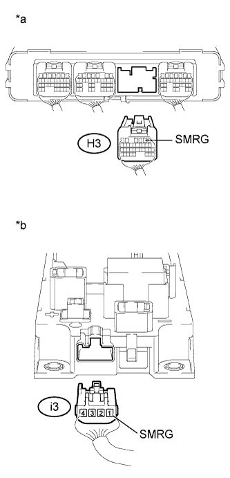 |
Measure the resistance according to the value(s) in the table below.
| *a | Rear view of wire harness connector (to Power Management Control ECU) |
| *b | Rear view of wire harness connector (to Hybrid Battery Junction Block Assembly) |
| Tester Connection | Switch Condition | Specified Condition |
| H3-2 (SMRG) - i3-1 (SMRG) | Power switch off | Below 1 Ω |
| Tester Connection | Switch Condition | Specified Condition |
| H3-2 (SMRG) and i3-1 (SMRG) - Body ground and other terminals | Power switch off | 10 kΩ or higher |
Connect the power management control ECU connector.
Connect the hybrid battery junction block assembly connector.
Install the upper hybrid battery cover sub-assembly.
|
| ||||
| OK | |
|
| 9.CHECK HARNESS AND CONNECTOR (HYBRID BATTERY JUNCTION BLOCK ASSEMBLY - BODY GROUND) |
Check that the service plug grip is not installed.
Remove the upper hybrid battery cover sub-assembly.
Disconnect connector i3 from the hybrid battery junction block assembly.
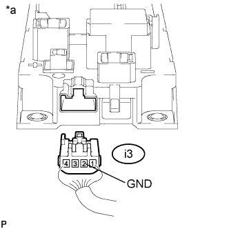 |
Measure the resistance according to the value(s) in the table below.
| Tester Connection | Switch Condition | Specified Condition |
| i3-2 (GND) - Body ground | Power switch off | Below 1 Ω |
| *a | Rear view of wire harness connector (to Hybrid Battery Junction Block Assembly) |
Connect the hybrid battery junction block assembly connector.
Install the upper hybrid battery cover sub-assembly.
|
| ||||
| OK | |
|
| 10.INSPECT HYBRID BATTERY JUNCTION BLOCK ASSEMBLY |
Check that the service plug grip is not installed.
Remove the hybrid battery junction block assembly.
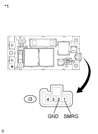 |
Measure the resistance according to the value(s) in the table below.
| Tester Connection | Condition | Specified Condition |
| i3-1 (SMRG) - i3-2 (GND) -40 to 80°C (104 to 176°F) | -40 to 80°C (-40 to 176°F) | 19.0 to 35.5 Ω |
| *1 | Hybrid Battery Junction Block Assembly |
Install the hybrid battery junction block assembly.
|
| ||||
| OK | ||
| ||
| ||
