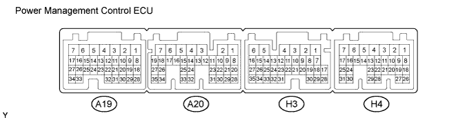
HYBRID CONTROL SYSTEM > TERMINALS OF ECU |
| Terminal No. (Symbol) | Wiring Color | Terminal Description | Condition | Specified Condition |
| A19-2 (+B2) - H3-6 (E1) | L - W-B | Power source | Power switch on (IG) | 11 to 14 V |
| A19-4 (FCTL) - H3-5 (E01) | BR - W-B | Cooling fan relay signal | Power switch on (IG) | Below 2 V |
| A19-11 (VLO) - H3-6 (E1) | R - W-B | DC/DC operation monitor / voltage change signal | Power switch on (IG) | Pulse generation (Waveform 1) |
| A19-13 (IWP) - H3-6 (E1) | G - W-B | Inverter water pump assembly signal | Power switch on (READY) | Pulse generation (Waveform 2) |
| A19-14 (NIWP) - H3-6 (E1) | P - W-B | Inverter water pump assembly signal | Power switch on (READY) | Pulse generation (Waveform 2) |
| A19-15 (BL) - H3-6 (E1) | LG - W-B | Back up light | Power switch on (IG), shift lever in R | 11 to 14 V |
| A19-16 (GI) - H3-6 (E1) | Y - W-B | Camshaft position sensor signal | Power switch on (READY), with engine running | Pulse generation (Waveform 3) |
| A19-19 (CLK) - H3-6 (E1) | G - W-B | A/C communication signal | Power switch on (READY), air conditioning system stopped | Pulse generation (Waveform 4) |
| A19-20 (STB) - H3-6 (E1) | W - W-B | A/C communication signal | Power switch on (READY), air conditioning system stopped | Pulse generation (Waveform 4) |
| A19-21 (NODD) - H3-6 (E1) | W - W-B | DC/DC operation | DC/DC converter operating normally | 5 to 7 V |
| A19-21 (NODD) - H3-6 (E1) | W - W-B | DC/DC operation | DC/DC converter not operating normally | 2 to 4 V |
| A19-21 (NODD) - H3-6 (E1) | W - W-B | DC/DC operation | DC/DC converter operating prohibited | 0.1 to 0.5 V |
| A19-24 (MMT) - A19-25 (MMTG) | L - BR | Motor temperature sensor | Power switch on (IG), temperature 25°C (77°F) | 3.6 to 4.6 V |
| A19-24 (MMT) - A19-25 (MMTG) | L - BR | Motor temperature sensor | Power switch on (IG), temperature 60°C (140°F ) | 2.2 to 3.2 V |
| A19-26 (GMT) - A19-27 (GMTG) | B - R | Generator temperature sensor | Power switch on (IG), temperature 25°C (77°F) | 3.6 to 4.6 V |
| A19-26 (GMT) - A19-27 (GMTG) | B - R | Generator temperature sensor | Power switch on (IG), temperature 60°C (140°F ) | 2.2 to 3.2 V |
| A19-29 (SI0) - H3-6 (E1) | Y - W-B | HV battery blower fan | Power switch on (IG), during Active Test | Pulse generation (Waveform 5) |
| A19-30 (ETI) - H3-6 (E1) | R - W-B | A/C communication signal | Power switch on (READY), air conditioning system stopped | Pulse generation (Waveform 4) |
| A19-31 (ITE) - H3-6 (E1) | Y - W-B | A/C communication signal | Power switch on (READY), air conditioning system stopped | Pulse generation (Waveform 4) |
| A19-32 (ILK) - H3-6 (E1) | V - W-B | Interlock switch | Power switch on (IG), inverter cover, high-voltage input cables and service plug grip installed correctly | 0 to 1.5 V |
| A19-32 (ILK) - H3-6 (E1) | V - W-B | Interlock switch | Power switch on (IG), inverter cover, high-voltage input cables or service plug grip not installed | 11 to 14 V |
| A20-1 (IG2) - H3-6 (E1) | R - W-B | Power source | Power switch on (IG) | 11 to 14 V |
| A20-2 (IG2D) - H3-6 (E1) | V - W-B | IG2 relay | Power switch on (IG) | 11 to 14 V |
| A20-5 (+B1) - H3-6 (E1) | L - W-B | Power source | Power switch on (IG) | 11 to 14 V |
| A20-6 (MREL) - H3-6 (E1) | BE - W-B | Main relay | Power switch on (IG) | 11 to 14 V |
| A20-7 (ST1-) - H3-6 (E1) | R - W-B | Brake cancel switch | Power switch on (IG), brake pedal depressed | 0 to 1.5 V |
| A20-7 (ST1-) - H3-6 (E1) | R - W-B | Brake cancel switch | Power switch on (IG), brake pedal released | 11 to 14 V |
| A20-18 (VCP1) - A20-34 (EP1) | Y - B | Accelerator pedal sensor assembly power source (for VPA1) | Power switch on (IG) | 4.5 to 5.5 V |
| A20-19 (VCP2) - A20-35 (EP2) | G - R | Accelerator pedal sensor assembly power source (for VPA2) | Power switch on (IG) | 4.5 to 5.5 V |
| A20-20 (CLK-) - H3-6 (E1) | W - W-B | MG communication clock signal | Power switch on (READY) | Pulse generation (Waveform 6) |
| A20-21 (CLK+) - H3-6 (E1) | B - W-B | MG communication clock signal | Power switch on (READY) | Pulse generation (Waveform 6) |
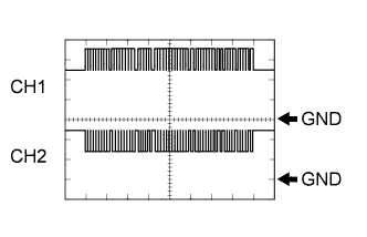
| A20-22 (PCON) - H3-6 (E1) | LG - W-B | P position switch signal | Power switch on (IG), park (P) selected | Pulse generation (Waveform 7) |
| A20-23 (STP) - H3-6 (E1) | L - W-B | Stop light switch | Brake pedal depressed | 11 to 14 V |
| A20-23 (STP) - H3-6 (E1) | L - W-B | Stop light switch | Brake pedal released | 0 to 1.5 V |
| A20-24 (HTM+) - H3-6 (E1) | B - W-B | Communication signal from power management control ECU (HV CPU) to MG ECU | Power switch on (READY) | Pulse generation (Waveform 8) |
| A20-25 (HTM-) - H3-6 (E1) | W - W-B | Communication signal from power management control ECU (HV CPU) to MG ECU | Power switch on (READY) | Pulse generation (Waveform 8) |
| A20-26 (VPA1) - A20-34 (EP1) | L - B | Accelerator pedal sensor assembly (for accelerator pedal position detection) | Power switch on (IG), accelerator pedal released | 0.4 to 1.4 V |
| A20-26 (VPA1) - A20-34 (EP1) | L - B | Accelerator pedal sensor assembly (for accelerator pedal position detection) | Power switch on (IG) engine stopped, park (P) selected, accelerator pedal fully depressed | 2.6 to 4.5 V |
| A20-27 (VPA2) - A20-35 (EP2) | W - R | Accelerator pedal sensor assembly (for accelerator pedal position detection) | Power switch on (IG), accelerator pedal released | 1.0 to 2.2 V |
| A20-27 (VPA2) - A20-35 (EP2) | W - R | Accelerator pedal sensor assembly (for accelerator pedal position detection) | Power switch on (IG) engine stopped, park (P) selected, accelerator pedal fully depressed | 3.4 to 5.3 V |
| A20-28 (PPOS) - H3-6 (E1) | V - W-B | P position switch signal | Power switch on (IG), park (P) selected | Pulse generation (Waveform 7) |
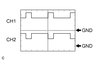
| A20-29 (MTH-) - H3-6 (E1) | W - W-B | Communication signal from MG ECU to power management control ECU (HV CPU) | Power switch on (READY) | Pulse generation (Waveform 9) |
| A20-30 (MTH+) - H3-6 (E1) | B - W-B | Communication signal from MG ECU to power management control ECU (HV CPU) | Power switch on (READY) | Pulse generation (Waveform 9) |
| A20-31 (HSDN) - H3-6 (E1) | B - W-B | MG ECU shutdown signal | Power switch on (READY) | 0 to 1.5 V |
| A20-32 (REQ-) - H3-6 (E1) | W - W-B | MG ECU communication request signal | Power switch on (READY) | Pulse generation (Waveform 10) |
| A20-33 (REQ+) - H3-6 (E1) | B - W-B | MG ECU communication request signal | Power switch on (READY) | Pulse generation (Waveform 10) |
| H3-1 (AM22) - H3-6 (E1) | W - W-B | Constant power source | Power switch on (IG) | 11 to 14 V |
| H3-1 (AM22) - H3-6 (E1) | W - W-B | Constant power source | Power switch on (READY) | 11 to 15.5 V |
| H3-2 (SMRG) - H3-5 (E01) | Y - W-B | System main relay | Power switch on (IG)→Power switch on (READY) | Pulse generation (Waveform 11) |
| H3-3 (SMRP) - H3-5 (E01) | W - W-B | System main relay | Power switch on (IG)→Power switch on (READY) | Pulse generation (Waveform 11) |
| H3-4 (SMRB) - H3-5 (E01) | SB - W-B | System main relay | Power switch on (IG)→Power switch on (READY) | Pulse generation (Waveform 11) |
| H3-7 (SSW1) - H3-6 (E1) | B - W-B | Power switch | Power switch pressed and held | 0 to 1.5 V |
| H3-11 (TC) - H3-6 (E1) | L - W-B | Diagnosis terminal | Power switch on (IG) | 11 to 14 V |
| H3-13 (EVSW) - H3-6 (E1) | B - W-B | EV switch signal | Power switch on (IG), EV switch not operated | 11 to 14 V |
| H3-13 (EVSW) - H3-6 (E1) | B - W-B | EV switch signal | Power switch on (IG), EV switch operated | 0 to 1.5 V |
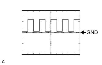
| H3-14 (SPDI) - H3-6 (E1) | V - W-B | Vehicle speed signal | Approximately 20 km/h (12 mph) | Pulse generation (Waveform 12) |
| H3-16 (P1) - H3-6 (E1) | Y - W-B | P position switch signal | Power switch on (IG), P position switch off | 7 to 12 V |
| H3-16 (P1) - H3-6 (E1) | Y - W-B | P position switch signal | Power switch on (IG), P position switch on | 3 to 5 V |
| H3-17 (VCX4) - H3-6 (E1) | P - W-B | Select sensor power source (VCX4) | Power switch on (IG) | 11 to 14 V |
| H3-18 (VSX4) - H3-6 (E1) | LG - W-B | Select sensor (Sub) | Power switch on (IG), shift lever in home position or B | 1.0 to 1.6 V |
| H3-18 (VSX4) - H3-6 (E1) | LG - W-B | Select sensor (Sub) | Power switch on (IG), shift lever in R, N or D | 2.9 to 4.3 V |
| H3-19 (VCX3) - H3-6 (E1) | W - W-B | Select sensor power source (VSX3) | Power switch on (IG) | 11 to 14 V |
| H3-20 (VSX3) - H3-6 (E1) | BR - W-B | Select sensor (Main) | Power switch on (IG), shift lever in home position or B | 1.0 to 1.6 V |
| H3-20 (VSX3) - H3-6 (E1) | BR - W-B | Select sensor (Main) | Power switch on (IG), shift lever in R, N or D | 2.9 to 4.3 V |
| H3-21 (VCX2) - H3-23 (E2X2) | SB - V | Shift sensor power source (VSX2) | Power switch on (IG) | 4.5 to 5.5 V |
| H3-22 (VSX2) - H3-23 (E2X2) | L - V | Shift sensor (Sub) | Power switch on (IG), shift lever in home position or N | 2.0 to 3.0 V |
| H3-22 (VSX2) - H3-23 (E2X2) | L - V | Shift sensor (Sub) | Power switch on (IG), shift lever in R | 0.3 to 1.8 V |
| H3-22 (VSX2) - H3-23 (E2X2) | L - V | Shift sensor (Sub) | Power switch on (IG), shift lever in B or D | 3.2 to 4.8 V |
| H3-25 (VSX1) - H3-24 (E2X1) | Y - P | Shift sensor (Main) | Power switch on (IG), shift lever in home position or N | 2.0 to 3.0 V |
| H3-25 (VSX1) - H3-24 (E2X1) | Y - P | Shift sensor (Main) | Power switch on (IG), shift lever in R | 0.3 to 1.8 V |
| H3-25 (VSX1) - H3-24 (E2X1) | Y - P | Shift sensor (Main) | Power switch on (IG), shift lever in B or D | 3.2 to 4.8 V |
| H3-26 (VCX1) - H3-24 (E2X1) | LG - P | Shift sensor power source (VSX1) | Power switch on (IG) | 4.5 to 5.5 V |
| H3-28 (THB) - H3-30 (ETHB) | L - V | Auxiliary battery temperature | Power switch on (IG), auxiliary battery temperature 25°C (77°F) | 1.7 to 2.3 V |
| H3-28 (THB) - H3-30 (ETHB) | L - V | Auxiliary battery temperature | Power switch on (IG), auxiliary battery temperature 60°C (140°F) | 0.6 to 0.9 V |
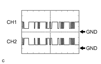
| H3-29 (ABFS) - H3-6 (E1) | B - W-B | Airbag activation signal | Power switch on (READY) (2 seconds after power switch on (ACC)) | Pulse generation (Waveform 13) |
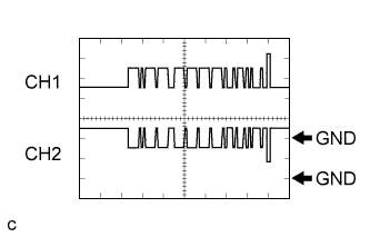
| H3-32 (BTH+) - H3-6 (E1) | R - W-B | Communication signal from battery smart unit to power management control ECU (HV CPU) | Power switch on (IG) | Pulse generation (Waveform 14) |
| H3-33 (BTH-) - H3-6 (E1) | G - W-B | Communication signal from battery smart unit to power management control ECU (HV CPU) | Power switch on (IG) | Pulse generation (Waveform 14) |
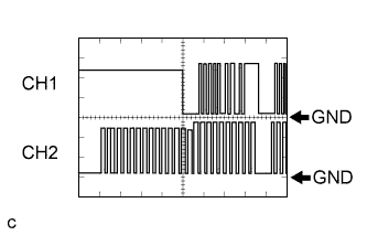
| H3-34 (CA2H) - H3-6 (E1) | R - W-B | CAN communication signal | Power switch on (IG) | Pulse generation (Waveform 15) |
| H3-35 (CA2L) - H3-6 (E1) | B - W-B | CAN communication signal | Power switch on (IG) | Pulse generation (Waveform 15) |
| H4-1 (ACCD) - H3-6 (E1) | G - W-B | ACC relay | Power switch on (ACC) | 11 to 14 V |
| H4-2 (IG1D) - H3-6 (E1) | B - W-B | IG1 relay | Power switch on (IG) | 11 to 14 V |
| H4-7 (AM21) - H3-6 (E1) | W - W-B | Constant power source | Power switch on (IG) | 11 to 14 V |
| H4-7 (AM21) - H3-6 (E1) | W - W-B | Constant power source | Power switch on (READY) | 11 to 15.5 V |
| H4-11 (LIN2) - H3-6 (E1) | B - W-B | LIN communication signal | Power switch on (IG) | Pulse generation |
| H4-17 (SSW2) - H3-6 (E1) | Y - W-B | Power switch | Power switch pressed and held | 0 to 1.5 V |
| H4-20 (IMO) - H3-6 (E1) | L - W-B | Immobiliser communication | Immobiliser communicating | Pulse generation (Waveform 16) |
| H4-21 (IMI) - H3-6 (E1) | R - W-B | Immobiliser communication | Immobiliser communicating | Pulse generation (Waveform 16) |
| H4-24 (CA1L) - H3-6 (E1) | V - W-B | CAN communication signal | Power switch on (IG) | Pulse generation (Waveform 17) |
| H4-25 (CA1H) - H3-6 (E1) | P - W-B | CAN communication signal | Power switch on (IG) | Pulse generation (Waveform 17) |
| H4-30 (CA3N) - H3-6 (E1) | L - W-B | CAN communication signal | Power switch on (IG) | Pulse generation (Waveform 18) |
| H4-31 (CA3P) - H3-6 (E1) | LG - W-B | CAN communication signal | Power switch on (IG) | Pulse generation (Waveform 18) |
| Oscilloscope waveforms |
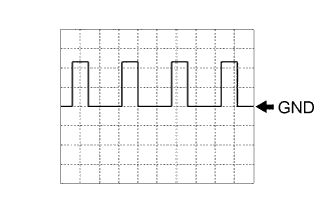 |
Waveform 1 (DC/DC operation monitor / voltage change signal)
| Item | Content |
| Terminal | A19-11 (VLO) - H3-6 (E1) |
| Equipment Setting | 5 V/DIV., 50 ms./DIV. |
| Condition | Power switch on (IG) |
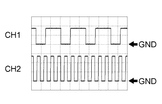 |
Waveform 2 (Inverter water pump assembly signal)
| Item | Content |
| Terminal | CH1: A19-13 (IWP) - H3-6 (E1) CH2: A19-14 (NIWP) - H3-6 (E1) |
| Equipment Setting | 5 V/DIV., 50 ms./DIV. |
| Condition | Power switch on (READY) |
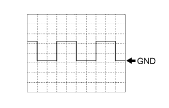 |
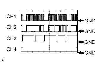
Waveform 3 (GI signal)
| Item | Content |
| Terminal | A19-16 (GI) - H3-6 (E1) |
| Equipment Setting | 5 V/DIV., 20 ms./DIV. |
| Condition | Power switch on (READY) with engine running |
 |
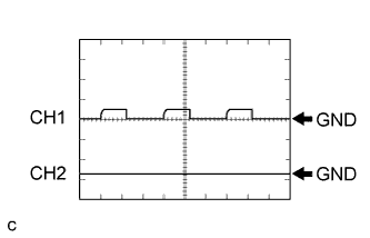
Waveform 4 (A/C communication signal)
| Item | Content |
| Terminal | CH1: A19-19 (CLK) - H3-6 (E1) CH2: A19-31 (ITE) - H3-6 (E1) CH3: A19-30 (ETI) - H3-6 (E1) CH4: A19-20 (STB) - H3-6 (E1) |
| Equipment Setting | 10 V/DIV., 100 ms./DIV. |
| Condition | Power switch on (READY) with air conditioning system stopped |
 |
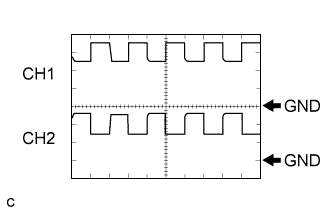
Waveform 5 (HV battery blower fan operation signal)
| Item | Content |
| Terminal | CH1: A19-29 (SI0) - H3-6 (E1) CH2: A19-4 (FCTL) - H3-5 (E01) |
| Equipment Setting | 10 V/DIV., 1 ms./DIV. |
| Condition | Power switch on (READY), with air conditioning system stopped |
 |
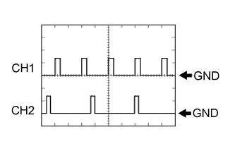
Waveform 6 (MG communication clock signal)
| Item | Content |
| Terminal | CH1: A20-21 (CLK+) - H3-6 (E1) CH2: A20-20 (CLK-) - H3-6 (E1) |
| Equipment Setting | 1 V/DIV., 1 μs./DIV. |
| Condition | Power switch on (READY) |
 |
Waveform 7 (P position signal)
| Item | Content |
| Terminal | CH1: A20-22 (PCON) - H3-6 (E1) CH2: A20-28 (PPOS) - H3-6 (E1) |
| Equipment Setting | 10 V/DIV., 10 ms./DIV. |
| Condition | Power switch on (IG) |
 |
Waveform 8 (communication signal from power management control ECU (HV CPU) to MG ECU)
| Item | Content |
| Terminal | CH1: A20-24 (HTM+) - H3-6 (E1) CH2: A20-25 (HTM-) - H3-6 (E1) |
| Equipment Setting | 1 V/DIV., 200 μs./DIV. |
| Condition | Power switch on (READY) |
|
Waveform 9 (communication signal from MG ECU to power management control ECU (HV CPU))
| Item | Content |
| Terminal | CH1: A20-30 (MTH+) - H3-6 (E1) CH2: A20-29 (MTH-) - H3-6 (E1) |
| Equipment Setting | 1 V/DIV., 200 μs./DIV. |
| Condition | Power switch on (READY) |
 |
Waveform 10 (MG ECU communication request signal)
| Item | Content |
| Terminal | CH1: A20-33 (REQ+) - H3-6 (E1) CH2: A20-32 (REQ-) - H3-6 (E1) |
| Equipment Setting | 1 V/DIV., 1 ms./DIV. |
| Condition | Power switch on (READY) |
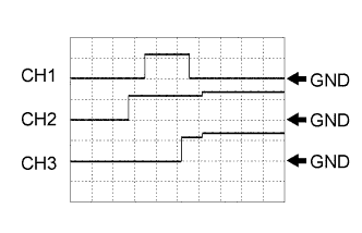 |
Waveform 11 (system main relay operation signal)
| Item | Content |
| Terminal | CH1: H3-3 (SMRP) - H3-5 (E01) CH2: H3-4 (SMRB) - H3-5 (E01) CH3: H3-2 (SMRG) - H3-5 (E01) |
| Equipment Setting | 10 V/DIV., 200 ms./DIV. |
| Condition | Power switch on (IG) → Power switch on (READY) |
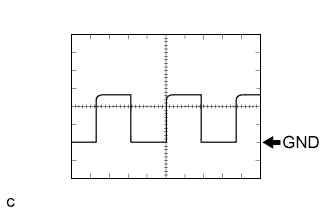 |
Waveform 12 (vehicle speed signal)
| Item | Content |
| Terminal | H3-14 (SPDI) - H3-6 (E1) |
| Equipment Setting | 5 V/DIV., 20 ms./DIV. |
| Condition | Driving at approximately 20 km/h (12 mph) with power switch on (READY) |
 |
Waveform 13 (airbag deployment signal)
| Item | Content |
| Terminal | H3-29 (ABFS) - H3-6 (E1) |
| Equipment Setting | 5 V/DIV., 500 ms./DIV. |
| Condition | Power switch on (READY) |
 |
Waveform 14 (communication signal from battery smart unit to power management control ECU (HV CPU))
| Item | Content |
| Terminal | CH1: H3-32 (BTH+) - H3-6 (E1) CH2: H3-33 (BTH-) - H3-6 (E1) |
| Equipment Setting | 2 V/DIV., 500 μs./DIV. |
| Condition | Power switch on (IG) |
 |
Waveform 15 (CAN communication signal)
| Item | Content |
| Terminal | CH1: H3-34 (CA2H) - H3-6 (E1) CH2: H3-35 (CA2L) - H3-6 (E1) |
| Equipment Setting | 1 V/DIV., 50 μs./DIV. |
| Condition | Power switch on (IG) |
 |
Waveform 16 (immobiliser communication signal)
| Item | Content |
| Terminal | CH1: H4-20 (IMO) - H3-6 (E1) CH2: H4-21 (IMI) - H3-6 (E1) |
| Equipment Setting | 5 V/DIV., 200 ms./DIV. |
| Condition | Power switch off → Power switch on (IG) → Power switch on (READY) |
|
Waveform 17 (CAN communication signal)
| Item | Content |
| Terminal | CH1: H4-25 (CA1H) - H3-6 (E1) CH2: H4-24 (CA1L) - H3-6 (E1) |
| Equipment Setting | 1 V/DIV., 50 μs./DIV. |
| Condition | Power switch on (IG) |
|
Waveform 18 (CAN communication signal)
| Item | Content |
| Terminal | CH1: H4-31 (CA3P) - H3-6 (E1) CH2: H4-30 (CA3N) - H3-6 (E1) |
| Equipment Setting | 1 V/DIV., 50 μs./DIV. |
| Condition | Power switch on (IG) |
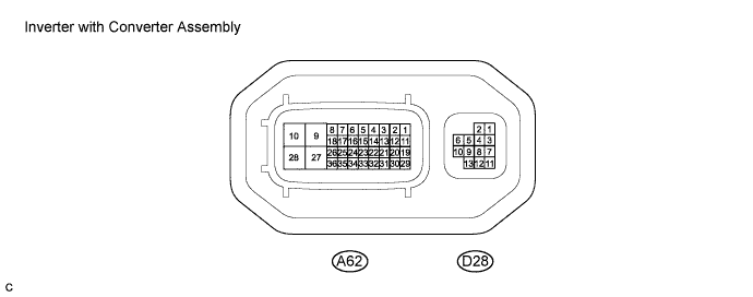
| Terminal No. (Symbol) | Wiring Color | Terminal Description | Condition | Standard Condition |
| A62-1 (IGCT) - A62-28 (GND1) | B - W-B | MG ECU power source | Power switch on (IG) | 11 to 14 V |
| A62-2 (IDH) - A62-28 (GND1) | L - W-B | PTC heater prohibit signal | Power switch on (IG) | 4 to 6 V |
| A62-3 (VLO) - A62-28 (GND1) | R - W-B | DC/DC operation monitor / voltage change signal | Power switch on (IG) | Pulse generation (Waveform 1) |
| A62-5 (CLK+) - A62-28 (GND1) | B - W-B | Communication clock signal | Power switch on (READY) | Pulse generation (Waveform 2) |
| A62-6 (REQ+) - A62-28 (GND1) | B - W-B | Communication request signal | Power switch on (READY) | Pulse generation (Waveform 3) |
| A62-7 (MTH+) - A62-28 (GND1) | B - W-B | Communication signal from MG ECU to power management control ECU (HV CPU) | Power switch on (READY) | Pulse generation (Waveform 4) |
| A62-8 (HTM+) - A62-28 (GND1) | B - W-B | Communication signal from power management control ECU (HV CPU) to MG ECU | Power switch on (READY) | Pulse generation (Waveform 5) |
| A62-11 (S) - A62-28 (GND1) | W - W-B | Auxiliary battery voltage monitor | Power switch on (IG) | 11 to 14 V |
| A62-12 (NODD) - A62-28 (GND1) | W - W-B | DC/DC operation | DC/DC converter operating normally | 5 to 7 V |
| A62-12 (NODD) - A62-28 (GND1) | W - W-B | DC/DC operation | DC/DC converter not operating normally | 2 to 4 V |
| A62-12 (NODD) - A62-28 (GND1) | W - W-B | DC/DC operation | DC/DC converter operation prohibited | 0.1 to 0.5 V |
| A62-15 (CLK-) - A62-28 (GND1) | W - W-B | Communication clock signal | Power switch on (READY) | Pulse generation (Waveform 2) |
| A62-16 (REQ-) - A62-28 (GND1) | W - W-B | Communication request signal | Power switch on (READY) | Pulse generation (Waveform 3) |
| A62-17 (MTH-) - A62-28 (GND1) | W - W-B | Communication signal from MG ECU to power management control ECU (HV CPU) | Power switch on (READY) | Pulse generation (Waveform 4) |
| A62-18 (HTM-) - A62-28 (GND1) | W - W-B | Communication signal from power management control ECU (HV CPU) to MG ECU | Power switch on (READY) | Pulse generation (Waveform 5) |
| A62-29 (GI) - A62-28 (GND1) | B - W-B | GI signal | Power switch on (READY), with engine running | Pulse generation (Waveform 6) |
| A62-31 (HSDN) - A62-28 (GND1) | B - W-B | MG shutdown signal | Power switch on (READY) | 0 to 1 V |
| A62-35 (ILKI) - A62-28 (GND1) | V - W-B | Interlock switch signal | Power switch on (IG), inverter cover, high-voltage input cables and service plug grip installed correctly | Below 1 V |
| A62-35 (ILKI) - A62-28 (GND1) | V - W-B | Interlock switch signal | Power switch on (IG), inverter cover, high-voltage input cables or service plug grip not installed | 11 to 14 |
| A62-36 (ILKO) - A62-28 (GND1) | LG - W-B | Interlock switch signal | Power switch on (IG), inverter cover, high-voltage input cables and service plug grip installed correctly | Below 1 V |
| A62-36 (ILKO) - A62-28 (GND1) | LG - W-B | Interlock switch signal | Power switch on (IG), inverter cover, high-voltage input cables or service plug grip not installed | 11 to 14 |
| A62-9 (+B2) - A62-28 (GND1) | R - W-B | MG ECU power source | Power switch on (IG) | 11 to 14 V |
| A62-10 (+B) - A62-28 (GND1) | R - W-B | MG ECU power source | Power switch on (IG) | 11 to 14 V |
| D28-1 (MRF) - D28-2 (MRFG) | Y - L | Motor resolver signal | Motor resolver running | Pulse generation (Waveform 7) |
| D28-3 (MSN) - D28-4 (MSNG) | G - W | Motor resolver signal | Motor resolver running | Pulse generation (Waveform 7) |
| D28-6 (MCS) - D28-5 (MCSG) | R - BR | Motor resolver signal | Motor resolver running | Pulse generation (Waveform 7) |
| D28-7 (GSN) - D28-8 (GSNG) | B - V | Generator resolver signal | Generator resolver running | Pulse generation (Waveform 8) |
| D28-10 (GCS) - D28-9 (GCSG) | GR - LG | Generator resolver signal | Generator resolver running | Pulse generation (Waveform 8) |
| D28-11 (GRF) - D28-12 (GRFG) | P - BE | Generator resolver signal | Generator resolver running | Pulse generation (Waveform 8) |
| Oscilloscope waveforms |
|
Waveform 1 (DC/DC operation monitor / voltage change signal)
| Item | Content |
| Terminal | A62-3 (VLO) - A62-28 (GND1) |
| Equipment Setting | 5 V/DIV., 50 ms./DIV. |
| Condition | Power switch on (IG) |
|
Waveform 2 (MG ECU communication clock signal)
| Item | Content |
| Terminal | CH1: A62-5 (CLK+) - A62-28 (GND1) CH2: A62-15 (CLK-) - A62-28 (GND1) |
| Equipment Setting | 1 V/DIV., 1 μs./DIV. |
| Condition | Power switch on (READY) |
|
Waveform 3 (MG ECU communication request signal)
| Item | Content |
| Terminal | CH1: A62-6 (REQ+) - A62-28 (GND1) CH2: A62-16 (REQ-) - A62-28 (GND1) |
| Equipment Setting | 1 V/DIV., 1 ms./DIV. |
| Condition | Power switch on (READY) |
|
Waveform 4 (communication signal from MG ECU to power management control ECU (HV CPU))
| Item | Content |
| Terminal | CH1: A62-7 (MTH+) - A62-28 (GND1) CH2: A62-17 (MTH-) - A62-28 (GND1) |
| Equipment Setting | 1 V/DIV., 200 μs./DIV. |
| Condition | Power switch on (READY) |
|
Waveform 5 (communication signal from power management control ECU (HV CPU) to MG ECU)
| Item | Content |
| Terminal | CH1: A62-8 (HTM+) - A62-28 (GND1) CH2: A62-18 (HTM-) - A62-28 (GND1) |
| Equipment Setting | 1 V/DIV., 200 μs./DIV. |
| Condition | Power switch on (READY) |
|
Waveform 6 (GI signal)
| Item | Content |
| Terminal | A62-29 (GI) - A62-28 (GND1) |
| Equipment Setting | 5 V/DIV., 20 ms./DIV. |
| Condition | Power switch on (READY) with engine running |
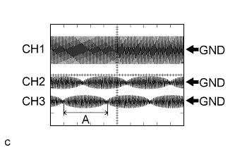 |
Waveform 7 (motor resolver signal)
| Item | Content |
| Terminal | CH1: D28-1 (MRF) - D28-2 (MRFG) CH2: D28-3 (MSN) - D28-4 (MSNG) CH3: D28-6 (MCS) - D28-5 (MCSG) |
| Equipment Setting | CH1: 10 V/DIV., 1 ms./DIV. CH2, 3: 5 V/DIV., 1 ms./DIV. |
| Condition | Resolver running |
|
Waveform 8 (generator resolver signal)
| Item | Content |
| Terminal | CH1: D28-11 (GRF) - D28-12 (GRFG) CH2: D28-7 (GSN) - D28-8 (GSNG) CH3: D28-10 (GCS) - D28-9 (GCSG) |
| Equipment Setting | CH1: 10 V/DIV., 1 ms./DIV. CH2, 3: 5 V/DIV., 1 ms./DIV. |
| Condition | Resolver running |