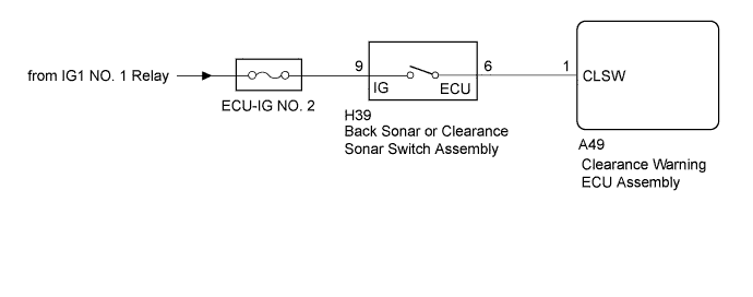
LEXUS PARKING ASSIST-SENSOR SYSTEM > Clearance Sonar Main Switch Circuit |
| 1.READ VALUE USING INTELLIGENT TESTER |
Connect the intelligent tester to the DLC3.
Turn the power switch on (IG).
Turn the intelligent tester on.
Enter the following menus: Body / Clearance Sonar / Data List.
According to the display on the intelligent tester, read the Data List.
| Tester Display | Measurement Item/Range | Normal Condition | Diagnostic Note |
| Main Switch | Clearance sonar main switch/OFF or ON | OFF: Clearance sonar main switch off ON: Clearance sonar main switch on | - |
| Clearance Sonar ECU Type | Type of clearance sonar ECU/Normal | Normal: Normal clearance sonar type | - |
| Result | Proceed to |
Both of the following conditions are met:
| A |
| "Normal" is not displayed. | B |
Both of the following conditions are met:
| C |
|
| ||||
|
| ||||
| A | ||
 | ||
| ||
| 2.INSPECT BACK SONAR OR CLEARANCE SONAR SWITCH ASSEMBLY |
Remove the back sonar or clearance sonar switch assembly (Click here).
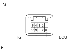 |
Measure the resistance according to the value(s) in the table below.
| Tester Connection | Switch Condition | Specified Condition |
| 9 (IG) - 6 (ECU) | Clearance sonar main switch is pushed | Below 1 Ω |
| 9 (IG) - 6 (ECU) | Clearance sonar main switch is not pushed | 10 kΩ or higher |
| *a | Component without harness connected (Back Sonar or Clearance Sonar Switch Assembly) |
|
| ||||
| OK | |
 |
| 3.CHECK HARNESS AND CONNECTOR (BACK SONAR OR CLEARANCE SONAR SWITCH ASSEMBLY POWER SOURCE) |
Measure the voltage according to the value(s) in the table below.
| Tester Connection | Condition | Specified Condition |
| H39-9 (IG) - Body ground | Power switch on (IG) | 11 to 14 V |
| H39-9 (IG) - Body ground | Power switch off | Below 1 V |
|
| ||||
| OK | |
|
| 4.CHECK HARNESS AND CONNECTOR (BACK SONAR OR CLEARANCE SONAR SWITCH ASSEMBLY - ECU) |
Measure the resistance according to the value(s) in the table below.
| Tester Connection | Condition | Specified Condition |
| A49-1 (CLSW) - H39-6 (ECU) | Always | Below 1 Ω |
| A49-1 (CLSW) - Body ground | Always | 10 kΩ or higher |
|
| ||||
| OK | ||
| ||
| ||

