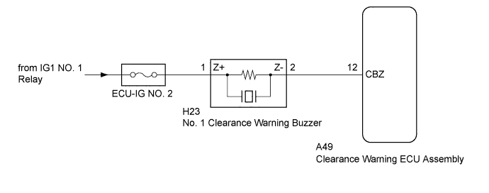
LEXUS PARKING ASSIST-SENSOR SYSTEM > Clearance Warning Buzzer Circuit |
| 1.PERFORM ACTIVE TEST USING INTELLIGENT TESTER |
Connect the intelligent tester to the DLC3.
Turn the power switch on (IG).
Turn the LEXUS parking assist-sensor system on.
Turn the intelligent tester on.
Enter the following menus: Body / Clearance Sonar / Active Test.
Check that the buzzer operates by performing the Active Test.
| Tester Display | Test Part | Control Range | Diagnostic Note |
| Buzzer | No. 1 Clearance Warning Buzzer | Operate or Stop | Confirm that the vehicle is stopped and the power switch is on (IG) |
|
| ||||
| OK | ||
 | ||
| ||
| 2.CHECK HARNESS AND CONNECTOR (CLEARANCE WARNING BUZZER - BATTERY) |
Disconnect the H23 connector from the No. 1 Clearance Warning Buzzer.
Measure the voltage according to the value(s) in the table below.
| Tester Connection | Condition | Specified Condition |
| H23-1 (Z+) - Body ground | Power switch on (IG) | 11 to 14 V |
| H23-1 (Z+) - Body ground | Power switch off | Below 1 V |
|
| ||||
| OK | |
 |
| 3.CHECK HARNESS AND CONNECTOR (CLEARANCE WARNING ECU ASSEMBLY - CLEARANCE WARNING BUZZER) |
Disconnect the A49 connector from the clearance warning ECU assembly.
Measure the resistance according to the value(s) in the table below.
| Tester Connection | Condition | Specified Condition |
| A49-12 (CBZ) - H23-2 (Z-) | Always | Below 1 Ω |
| A49-12 (CBZ) - Body ground | Always | 10 kΩ or higher |
|
| ||||
| OK | |
|
| 4.REPLACE NO. 1 CLEARANCE WARNING BUZZER |
Replace the No. 1 clearance warning buzzer with a new or known good one (Click here).
| NEXT | |
|
| 5.PERFORM ACTIVE TEST USING INTELLIGENT TESTER |
Connect the intelligent tester to the DLC3.
Turn the power switch on (IG).
Turn the LEXUS parking assist-sensor system on.
Turn the intelligent tester on.
Enter the following menus: Body / Clearance Sonar / Active Test.
Check that the buzzer operates by performing the Active Test.
| Tester Display | Test Part | Control Range | Diagnostic Note |
| Buzzer | No. 1 clearance warning buzzer | Operate or Stop | Confirm that the vehicle is stopped and the power switch is on (IG) |
|
| ||||
| OK | ||
| ||
| ||

