INSTALLATION
Removal / installation
- HINT:
- Use the same procedures for the RHD and LHD.
- The procedures listed below are for the LHD.
- Use the same procedures for the RHD and LHD.
| 1. INSTALL CLUTCH MASTER CYLINDER PUSH ROD CLEVIS BUSHING |

Apply MP grease to the inside of a new clevis bushing.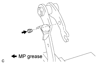

Install the clevis bushing to the clutch pedal.
- HINT:
- Install the clevis bushing from the left side of the vehicle.
| 2. INSTALL CLUTCH PEDAL PAD |
Install the clutch pedal pad to the clutch pedal.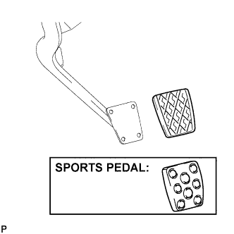
| 3. INSTALL CLUTCH PEDAL CUSHION (for LHD) |
Using needle-nose pliers, install the 3 clutch pedal cushions to the clutch pedal.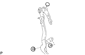
| 4. INSTALL CLUTCH PEDAL CUSHION (for RHD) |
Using needle-nose pliers, install the 4 clutch pedal cushions to the clutch pedal.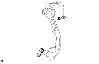
| 5. INSTALL CLUTCH PEDAL SHAFT COLLAR |
Apply MP grease to the inner, outer and end surfaces of 2 new pedal bushings.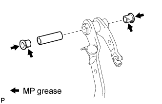
Install the clutch pedal shaft collar and 2 pedal bushings to the clutch pedal.
| 6. INSTALL CLUTCH PEDAL TURNOVER BUSHING |
Apply MP grease to the inside of the turnover bushing.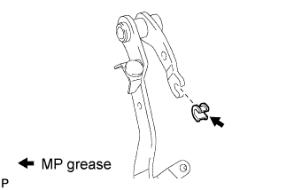
Install the turnover bushing to the clutch pedal.
| 7. INSTALL CLUTCH PEDAL SUB-ASSEMBLY |
Install the clutch pedal to the clutch pedal support with the pedal shaft, washer, and nut.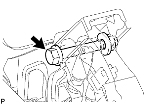
- Torque:
- 37 N*m{ 375 kgf*cm , 27 ft.*lbf }
| 8. INSTALL CLUTCH PEDAL SPRING HOLDER |
Apply MP grease to the inside of a new clutch pedal spring holder.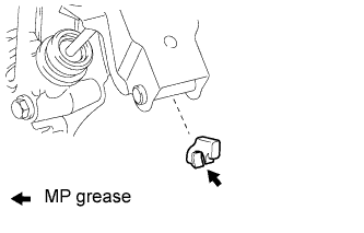
Install the clutch pedal spring holder.
| 9. INSTALL PEDAL WITH HOOK SPRING |
Apply MP grease to the sliding portion of the spring.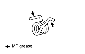
Install the hook spring.
| 10. INSTALL CLUTCH MASTER CYLINDER PUSH ROD CLEVIS PIN |
Apply MP grease to the contact surface of the pin and clevis bushing.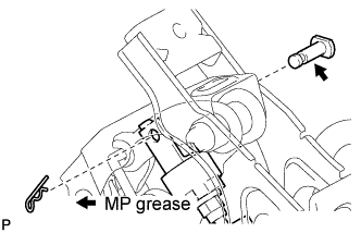
Connect the clevis to the clutch pedal with the pin.
- HINT:
- Install a pin from the left side of the vehicle.
Install the new clip to the pin.
| 11. INSTALL CLUTCH PEDAL SUPPORT SUB-ASSEMBLY (for LHD) |
Install the clutch pedal support with the 2 nuts and bolt.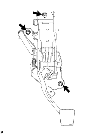
- Torque:
- Bolt:
- 24 N*m{ 242 kgf*cm , 17 ft.*lbf }
- Nut:
- 20 N*m{ 202 kgf*cm , 15 ft.*lbf }
| 12. INSTALL CLUTCH PEDAL SUPPORT SUB-ASSEMBLY (for RHD) |
Install the clutch pedal support with the 2 nuts and bolt.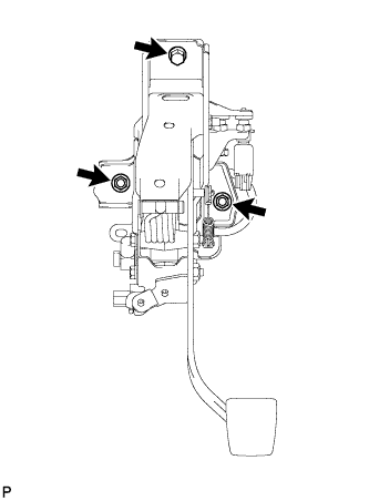
- Torque:
- Bolt:
- 24 N*m{ 242 kgf*cm , 17 ft.*lbf }
- Nut:
- 20 N*m{ 202 kgf*cm , 15 ft.*lbf }
| 13. CONNECT CLUTCH LINE |
Using SST, connect the clutch line.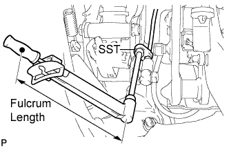
- SST
- 09023-00101
- Torque:
- 15 N*m{ 153 kgf*cm , 11 ft.*lbf }
- HINT:
- Use a torque wrench with a fulcrum length of 300 mm (11.81 in.).
| 14. CONNECT CLUTCH RESERVOIR TUBE (for LHD) |
Connect the clutch reservoir tube.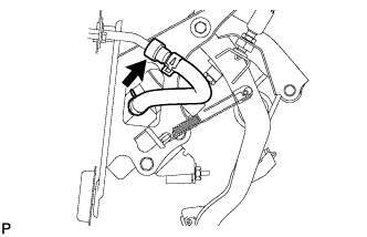
| 15. CONNECT CLUTCH RESERVOIR TUBE (for RHD) |
Connect the clutch reservoir tube.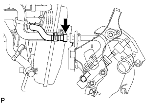
| 16. INSTALL WIRE HARNESS (for LHD) |
Connect the 3 connectors and clamp.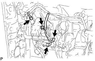
| 17. INSTALL WIRE HARNESS (for RHD) |
Connect the 2 connectors and clamp.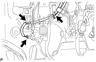
| 18. BLEED CLUTCH LINE |
Fill the brake reservoir with the brake fluid and bleed the clutch system (Click here).
- Torque:
- 11 N*m{ 110 kgf*cm , 8 ft.*lbf }
| 19. CHECK FOR BRAKE FLUID LEAKAGE |
- HINT:
- Check for leakage in the clutch system.
| 20. INSPECT AND ADJUST CLUTCH PEDAL HEIGHT |
| 21. INSTALL DRIVER SIDE KNEE AIRBAG ASSEMBLY |
Connect the connector.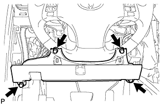
- NOTICE:
- When handling the airbag connector, take care not to damage the airbag wire harness.
Install the driver side knee airbag assembly with the 4 bolts.
- Torque:
- 10 N*m{ 102 kgf*cm , 7 ft.*lbf }
| 22. INSTALL LOWER INSTRUMENT PANEL FINISH PANEL SUB-ASSEMBLY |
Connect the connectors.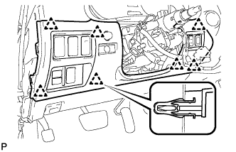
Engage the 7 clips and install the lower instrument panel finish panel sub-assembly.
| 23. INSTALL NO. 1 INSTRUMENT PANEL UNDER COVER SUB-ASSEMBLY |
Connect the connectors.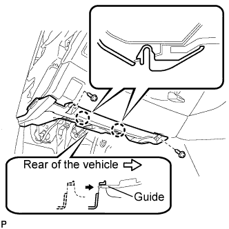
Insert the No. 1 instrument panel under cover sub-assembly into the guide as shown in the illustration.
Engage the 2 claws.
Install the No. 1 instrument panel under cover sub-assembly with the 2 screws <E>.
| 24. INSTALL SIDE INSTRUMENT PANEL LH |
Engage the 5 claws and 3 clips, and then install the side instrument panel LH.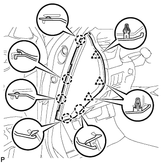
| 25. INSTALL FRONT DOOR OPENING TRIM COVER |
Engage the 6 claws and install the front door opening trim cover LH.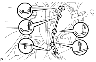
| 26. INSTALL FRONT DOOR SCUFF PLATE (w/o Illumination) |
Engage the 4 clips.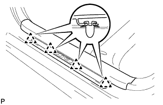
Engage the 7 claws, and install the front door scuff plate LH.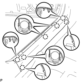
| 27. INSTALL FRONT DOOR SCUFF PLATE (w/ Illumination) |
Connect the connector.
Engage the 4 clips.
Engage the 7 claws, and install the front door scuff plate LH.
| 28. CONNECT CABLE TO BATTERY NEGATIVE TERMINAL |
| 29. CHECK BRAKE FLUID LEVEL IN RESERVOIR |
| 30. PERFORM INITIALIZATION |
| 31. INSPECT SRS WARNING LIGHT |