INSTALLATION
Removal / installation
| 1. INSTALL NO. 1 WINDSHIELD GLASS STOPPER |

Install 2 new stoppers to the vehicle body, as shown in the illustration.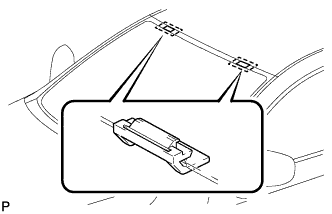

| 2. INSTALL NO. 2 WINDSHIELD GLASS STOPPER |
Coat the installation part of the stopper with Primer G.
- NOTICE:
- Allow the primer coating to dry for 3 minutes or more.
- Do not keep any of the opened Primer G for later use.
- Do not apply too much primer.
- Allow the primer coating to dry for 3 minutes or more.
Install 2 new windshield glass stoppers onto the glass, as shown in the illustration.
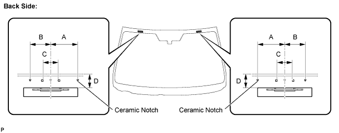
- Standard dimension:
Area
Dimension
A
40.0 mm (1.575 in.)
B
30.0 mm (1.181 in.)
C
25.0 mm (0.984 in.)
D
14.2 mm (0.559 in.)
| 3. INSTALL WINDSHIELD OUTSIDE MOULDING |
Using a brush or sponge, coat the edge of the glass and the contact surface with Primer G.
- NOTICE:
- Allow the primer coating to dry for 3 minutes or more.
- Do not coat the adhesive with Primer G.
- Do not keep any of the opened Primer G for later use.
- Allow the primer coating to dry for 3 minutes or more.
Install the windshield outside moulding, as shown in the illustration.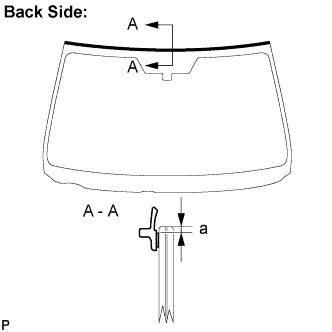
- Standard dimension:
Area
Dimension
a
2.0 mm (0.079 in.)
| 4. INSTALL WINDSHIELD GLASS ADHESIVE DAM |
Coat the installation part of the dam with Primer G.
- NOTICE:
- Allow the primer coating to dry for 3 minutes or more.
- Do not apply too much primer.
- Allow the primer coating to dry for 3 minutes or more.
Install a new dam, applying double-sided tape all the way around the glass except where the dam is installed, as shown in the illustration.
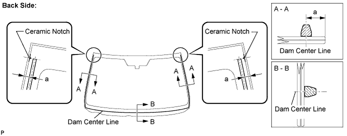
- Standard dimension:
Area
Dimension
a
9.5 mm (0.374 in.)
| 5. INSTALL WINDSHIELD GLASS |
Clean and shape the contact surface of the vehicle body.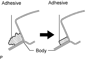
Using a knife, cut away any rough adhesive on the contact surface of the vehicle body to ensure the appropriate surface shape.
- NOTICE:
- Be careful not to damage the vehicle body.
- HINT:
- Leave as much adhesive on the vehicle body as possible.
Clean the contact surface of the vehicle body with a piece of shop rag saturated with cleaner.
- HINT:
- Even if all the adhesive has been removed, clean the vehicle body.
Position the glass.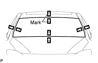
Using a suction cup, place the glass in the correct position.
Check that the whole contact surface of the glass rim is perfectly even.
Place reference marks between the glass and vehicle body.
- NOTICE:
- Check that the stoppers are attached to the vehicle body correctly.
- HINT:
- When reusing the glass, check and correct the reference mark positions.
Remove the glass.
Using a brush, coat the exposed part of the vehicle body on the vehicle side with Primer M.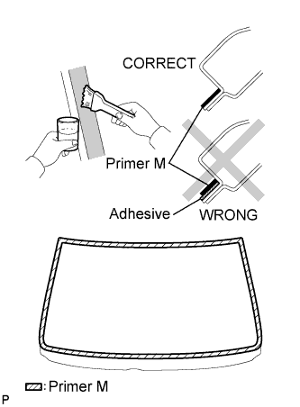
- NOTICE:
- Allow the primer coating to dry for 3 minutes or more.
- Do not coat the adhesive with Primer M.
- Do not keep any of the opened Primer M for later use.
- Allow the primer coating to dry for 3 minutes or more.
Using a brush or sponge, coat the edge of the glass and the contact surface with Primer G.
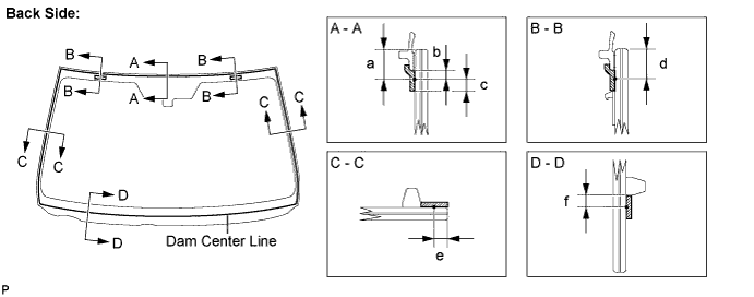
- Standard dimension:
Area
Dimension
a
10.2 mm (0.402 in.)
b
4.0 mm (0.158 in.)
c
7.0 mm (0.276 in.)
d
10.2 mm (0.402 in.)
e
3.0 mm (0.118 in.)
f
4.0 mm (0.158 in.)
- NOTICE:
- Allow the primer coating to dry for 3 minutes or more.
- Do not keep any of the opened Primer G for later use.
- Allow the primer coating to dry for 3 minutes or more.
- HINT:
- If an area other than that specified is coated by accident, wipe off the primer before it dries.
Apply adhesive (Adhesive: Part No. 08850-00801 or equivalent).
Cut off the tip of the cartridge nozzle, as shown in the illustration.
- HINT:
- After cutting off the tip, use all adhesive within the time described in the table below.
- Tack-free time:
Temperature
Tack-free Time
35°C (95°F)
15 minutes
20°C (68°F)
1 hour and 40 minutes
5°C (41°F)
8 hours
Load the sealer gun with the cartridge.
Coat the glass with adhesive, as shown in the illustration.
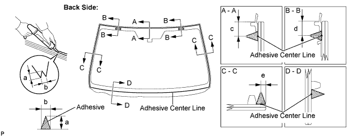
- Standard dimension:
Area
Dimension
a
12.0 mm (0.472 in.)
b
8.0 mm (0.315 in.)
c
10.2 mm (0.402 in.)
d
10.2 mm (0.402 in.)
e
3.0 mm (0.118 in.)
Install the glass.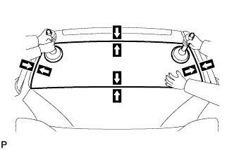
Using a suction cup, position the glass so that the reference marks are aligned, and press it in gently along the rim.
- NOTICE:
- Allow the primer coating to dry for 3 minutes or more.
- Check that the stoppers are attached to the vehicle body correctly.
- Check the clearance between the vehicle body and glass.
- Allow the primer coating to dry for 3 minutes or more.
Lightly press the front surface of the glass to ensure a close fit.
Using a scraper, remove any excess or protruding adhesive.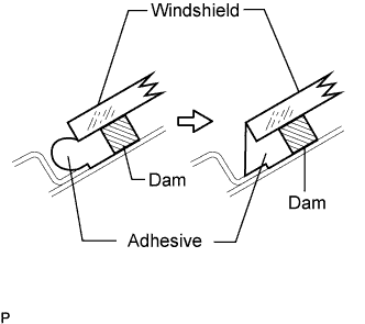
- NOTICE:
- Do not drive the vehicle for the time described in the table below.
- Minimum time:
Temperature
Minimum time prior to driving vehicle
35°C (95°F)
1 hour and 30 minutes
20°C (68°F)
5 hours
5°C (41°F)
24 hours
- HINT:
- Apply adhesive onto the glass rim.
| 6. CHECK FOR LEAKS AND REPAIR |
Conduct a leak test after the adhesive has completely hardened.
Seal any leaks with a sealer gun.
| 7. INSTALL ROOF HEADLINING ASSEMBLY (w/o Sliding Roof) |
Place the roof headlining in the vehicle from the front right door.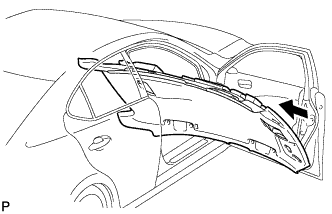
Engage the hook, 10 claws and 2 clips, and install the roof headlining assembly.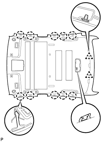
Connect the roof wire connector and engage each clamp.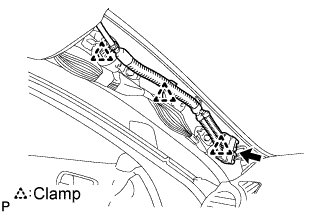
Connect each connector to the map light assembly.
| 8. INSTALL ROOF HEADLINING ASSEMBLY (w/ Sliding Roof) |
Place the roof headlining in the vehicle from the front right door.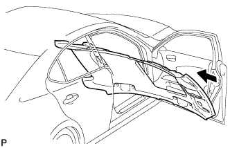
Engage the hook, 10 claws, 8 fasteners and 2 clips, and install the roof headlining assembly.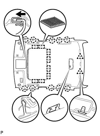
Connect the roof wire connector and engage each clamp.
Connect each connector to the map light assembly.
| 9. INSTALL RAIN SENSOR TAPE (w/ Rain Sensor) |
Peel off the releasing sheet (yellow side) and attach the rain sensor tape on the position indicated in the illustration (the sensor part of the rain sensor) while pushing out air bubbles with fingers.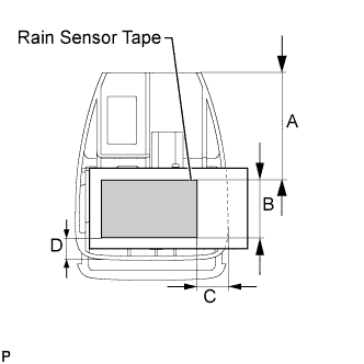
Peel off the releasing sheet (white side).
- NOTICE:
- When reusing the rain sensor, clean up dirt on the sensor part with a cloth, etc.
- Do not touch the sensor tape surface directly with fingers.
- When reusing the rain sensor, clean up dirt on the sensor part with a cloth, etc.
Area
Measurement
A
45.5 mm (1.791 in.)
B
24.7 mm (0.972 in.)
C
10.0 mm (0.393 in.)
D
9.8 mm (0.385 in.)
| 10. INSTALL RAIN SENSOR (w/ Rain Sensor) |
Connect the connector.
Engage the claw as shown in the illustration to set the position.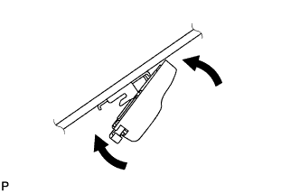
Gradually attach the rain sensor to the glass surface to prevent air bubbles from forming in between them.
Push in the stopper.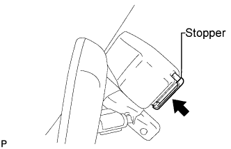
- NOTICE:
- Do not touch the sensor tape surface and the glass surface directly with fingers.
- Clean up dirt on the glass with a cloth, etc.
- After installing the rain sensor, there should be no air bubbles between the windshield glass and the rain sensor tape.
- Do not touch the sensor tape surface and the glass surface directly with fingers.
| 11. INSTALL VISOR HOLDER |
Set the claws of the visor holder as shown in the illustration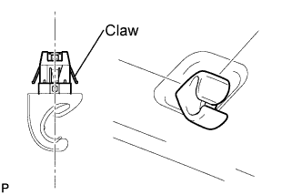
Engage the claws and install the visor holder.
- HINT:
- Use the same procedure to install the holder on the other side.
| 12. INSTALL VISOR ASSEMBLY LH |
Install the visor assembly LH with the 2 screws.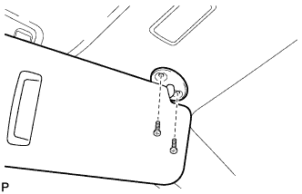
| 13. INSTALL VISOR ASSEMBLY RH |
| 14. INSTALL VISOR BRACKET COVER |
Engage the 4 claws and install the visor bracket cover.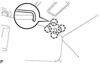
- HINT:
- Use the same procedure to install the cover on the other side.
| 15. INSTALL ASSIST GRIP SUB-ASSEMBLY |
Put an assist grip sub-assembly together as shown in the illustration.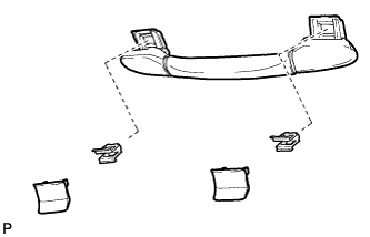
Install the assist grip sub-assembly.
- HINT:
- Use the same procedure for the other 3 assist grips.
| 16. INSTALL INNER REAR VIEW MIRROR ASSEMBLY (w/ EC Mirror) |
Using a "torx" socket wrench (T20), install the inner rear view mirror with the screw.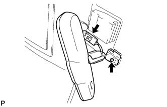
- Torque:
- 1.8 N*m{ 18 kgf*cm , 16 in.*lbf }
Connect the connector.
| 17. INSTALL INNER REAR VIEW MIRROR ASSEMBLY (w/o EC Mirror) |
Slide the inner rear view mirror assembly in the direction indicated by the arrow shown in the illustration to install it.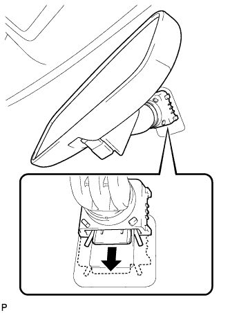
Engage the 2 claws and install the cover.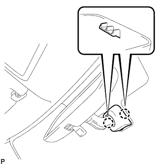
| 18. INSTALL MAP LIGHT ASSEMBLY (w/o Sliding Roof) |
Connect the connector.
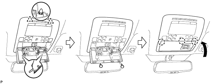
Engage the 2 clips and install the map light assembly.
Install the 2 screws.
Engage the 3 claws and close the cover.
| 19. INSTALL MAP LIGHT ASSEMBLY (w/ Sliding Roof) |
Connect the connector.
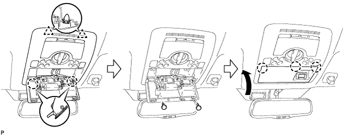
Engage the 2 clips and install the map light assembly.
Install the 2 screws.
Engage the 3 claws and close the cover.
| 20. INSTALL INNER REAR VIEW MIRROR STAY HOLDER COVER (w/ EC Mirror) |
Engage the 2 claws and install the inner rear view mirror stay holder cover as shown in the illustration.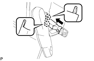
| 21. INSTALL FRONT PILLAR GARNISH RH |
| 22. INSTALL FRONT DOOR OPENING TRIM COVER RH |
Engage the 6 claws and install the front door opening trim cover RH.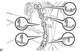
| 23. INSTALL FRONT DOOR SCUFF PLATE RH (w/o Illumination) |
| 24. INSTALL FRONT DOOR SCUFF PLATE RH (w/ Illumination) |
| 25. INSTALL FRONT PILLAR GARNISH LH |
Install a new clip <A> on the front pillar garnish LH.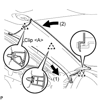
Engage the claw and 2 clips, and install the front pillar garnish LH.
| 26. INSTALL FRONT DOOR OPENING TRIM COVER LH |
Engage the 6 claws and install the front door opening trim cover LH.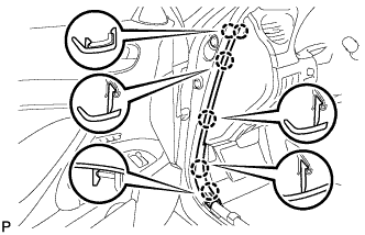
| 27. INSTALL FRONT DOOR SCUFF PLATE LH (w/o Illumination) |
Engage the 4 clips.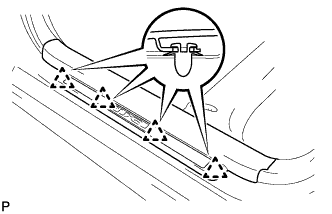
Engage the 7 claws, and install the front door scuff plate LH.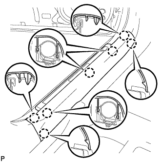
| 28. INSTALL FRONT DOOR SCUFF PLATE LH (w/ Illumination) |
Connect the connector.
Engage the 4 clips.
Engage the 7 claws, and install the front door scuff plate LH.
| 29. INSTALL COWL TOP VENTILATOR LOUVER SUB-ASSEMBLY |
Engage the 11 claws.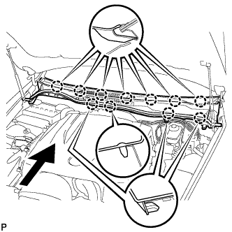
Install the cowl top ventilator louver sub-assembly with the 2 clips.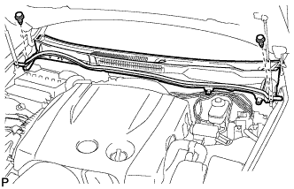
| 30. INSTALL FRONT WIPER ARM AND BLADE ASSEMBLY LH |
Operate the wiper, and stop the windshield wiper motor at the automatic stop position.
Clean the wiper arm serrations.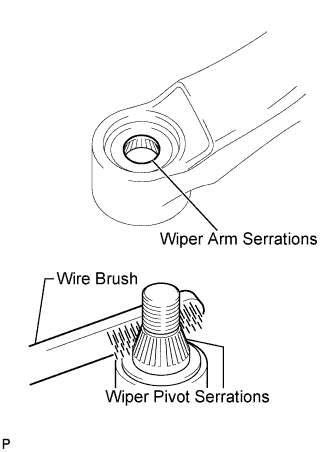
Clean the wiper pivot serrations with a wire brush (when reinstalling).
Install the front wiper arm and blade assembly LH with the nut at the position as shown in the illustration.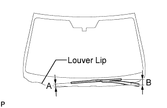
- Torque:
- 22 N*m{ 224 kgf*cm , 16 ft.*lbf }
- HINT:
- Hold the arm hinge by hand to fasten the nut.
Area
Measurement
A
15 to 30 mm (0.59 to 1.18 in.)
B
Approx. 40 mm (1.57 in.)
| 31. INSTALL FRONT WIPER ARM AND BLADE ASSEMBLY RH |
Operate the wiper, and stop the windshield wiper motor at the automatic stop position.
Clean the wiper arm serrations.
Clean the wiper pivot serrations with a wire brush (when reinstalling).
Install the front wiper arm and blade assembly RH with the nut at the position as shown in the illustration.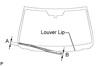
- Torque:
- 22 N*m{ 224 kgf*cm , 16 ft.*lbf }
- HINT:
- Hold the arm hinge by hand to fasten the nut.
Area
Measurement
A
18.5 to 33.5 mm (0.73 to 1.32 in.)
B
Approx. 20 mm (0.79 in.)
Operate the front wipers while spraying washer fluid on the windshield glass. Make sure that the front wipers function properly and there is no interference with the vehicle body.
| 32. INSTALL FRONT WIPER ARM HEAD CAP |
Install the front wiper arm head cap.
- HINT:
- Use the same procedures for the RH side and the LH side.
| 33. INSTALL NO. 1 WINDSHIELD MOULDING OUTSIDE CLIP |
| 34. INSTALL ROOF DRIP SIDE FINISH MOULDING LH |
| 35. INSTALL ROOF DRIP SIDE FINISH MOULDING RH |
| 36. INSTALL FRONT UPPER FENDER PROTECTOR LH |
Engage the claw and the 3 clips, then install the front upper fender protector LH.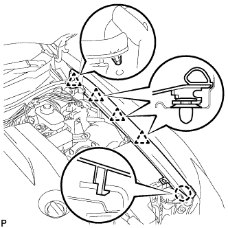
Engage the clip on the rubber portion of the cowl top ventilator louver sub-assembly to the front fender protector upper LH.
| 37. INSTALL FRONT UPPER FENDER PROTECTOR RH |
- HINT:
- Use the same procedures for the RH side and the LH side.
| 38. INSTALL SIDE ENGINE ROOM COVER RH |
Install the side cover with the 2 clips.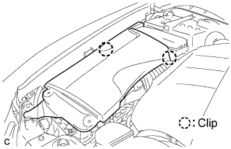
| 39. INSTALL SIDE ENGINE ROOM COVER LH |
Install the side cover with the 5 clips.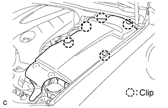
| 40. INSTALL COOL AIR INTAKE DUCT SEAL |
Install the intake duct seal with the 11 clips.