INSTALLATION
Removal / installation
| 1. INSTALL TRANSMISSION FLOOR SHIFT ASSEMBLY |

Install the floor shift assembly with the 4 bolts.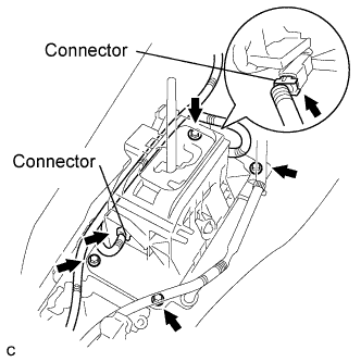

- Torque:
- 8.3 N*m{ 85 kgf*cm , 73 in.*lbf }
Connect the connector to the floor shift assembly.
| 2. INSTALL FLOOR SHIFT GEAR SHIFTING ROD SUB-ASSEMBLY |
Install the floor shift gear shifting rod sub-assembly with the nut.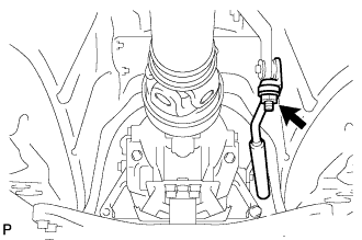
- Torque:
- 13 N*m{ 133 kgf*cm , 9 ft.*lbf }
| 3. INSTALL FRONT FLOOR NO. 1 HEAT INSULATOR |
Install the No. 1 heat insulator with the 4 nuts.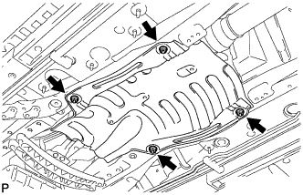
- Torque:
- 5.4 N*m{ 55 kgf*cm , 48 in.*lbf }
| 4. INSTALL FRONT EXHAUST PIPE ASSEMBLY |
Using a vernier caliper, measure the free length of the compression springs.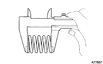
- Minimum length:
- 38.5 mm (1.516 in.)
Install a new gasket to the rear end of the front exhaust pipe.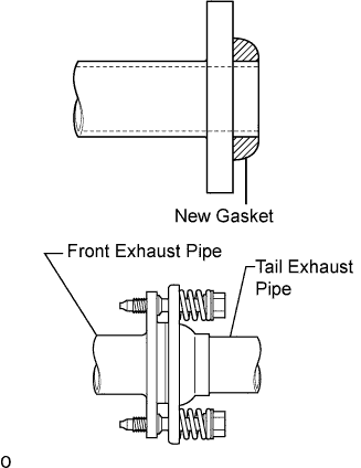
- NOTICE:
- Be careful with the installation direction of the gasket.
- Be careful with the installation direction of the gasket.
- Do not reuse the gasket.
- Do not reuse the gasket.
- To ensure a proper seal, do not use the tail exhaust pipe to force the gasket onto the front exhaust pipe.
- HINT:
- Using a plastic hammer, uniformly strike the gasket so that the gasket and front exhaust pipe are properly fit.
- To ensure a proper seal, do not use the tail exhaust pipe to force the gasket onto the front exhaust pipe.
Install 3 new gaskets and front exhaust pipe assembly.
- CAUTION:
- Do not reuse the gaskets.
Install the 2 bolts and 2 compression springs.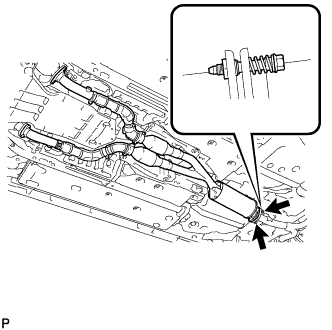
- Torque:
- 43 N*m{ 438 kgf*cm , 32 ft.*lbf }
Install 4 new nuts and 4 bolts.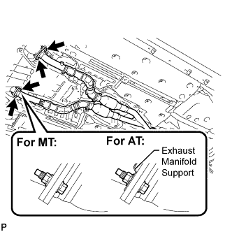
- Torque:
- 62 N*m{ 632 kgf*cm , 46 ft.*lbf }
- NOTICE:
- Do not reuse the nuts.
| 5. INSTALL OXYGEN SENSOR |
Before installing the heated oxygen sensors, twist the sensor wires counterclockwise 4 turns.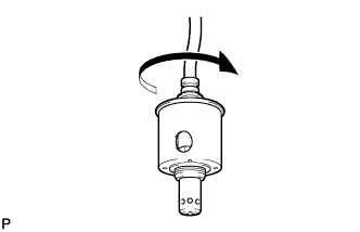
Using the SST, install the heated oxygen sensors to the front exhaust pipe.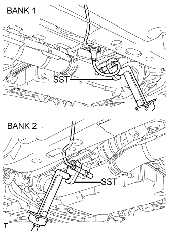
- SST
- 09224-00010
- Torque:
- 44 N*m{ 449 kgf*cm , 33 ft.*lbf }
After installing the sensors, check that the sensor wires are not twisted.
If the sensor wires are twisted, reinstall them.
Install the grommets of the heated oxygen sensors.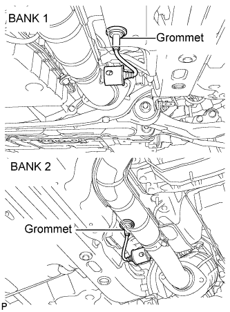
| 6. INSTALL FRONT CENTER FLOOR BRACE |
Install the front center floor brace with the 4 bolts.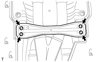
- Torque:
- 7.4 N*m{ 75 kgf*cm , 65 in.*lbf }
| 7. INSTALL REAR NO. 1 FLOOR PANEL BRACE |
Install the rear No. 1 floor panel brace with the 4 bolts.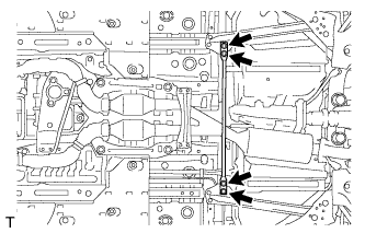
- Torque:
- 19 N*m{ 194 kgf*cm , 14 ft.*lbf }
| 8. INSTALL NO. 2 CONSOLE BOX DUCT |
Install the No. 2 console box duct with the 2 clips.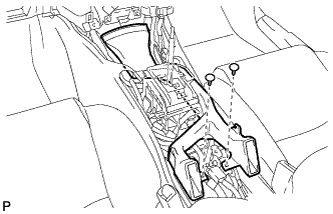
| 9. INSTALL CONSOLE BOX |
Engage the 2 claws and 2 clips.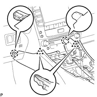
Install the 2 bolts <C>.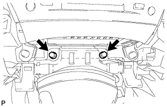
Install the 2 bolts <C>.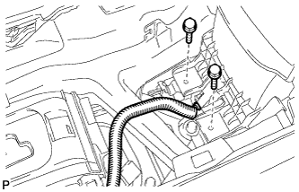
Connect the connector.
Connect the connectors.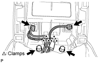
Engage the 2 clamps.
Install the 2 bolts <C>.
| 10. INSTALL CONSOLE BOX REGISTER ASSEMBLY |
Engage the 2 claws and 4 clips, and then install the console box register assembly.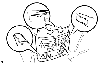
Install the rear ash receptacle assembly.
| 11. INSTALL FRONT ASH RECEPTACLE SUB-ASSEMBLY |
Connect the connectors.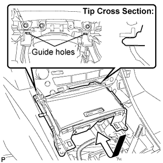
Insert the protruding parts of the front ash receptacle sub-assembly into the 2 guide holes as shown in the illustration.
Install the front ash receptacle sub-assembly with the 2 screws <F>.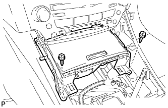
| 12. INSTALL CONSOLE PANEL SUB-ASSEMBLY |
Connect the connectors.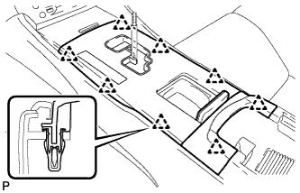
Engage the 8 clips and install the console panel sub-assembly.
| 13. INSTALL UPPER NO. 2 CONSOLE PANEL GARNISH |
Engage the claw and 2 clips, and then install the upper No. 2 console panel garnish.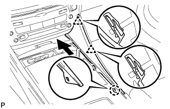
| 14. INSTALL UPPER NO. 1 CONSOLE PANEL GARNISH |
Engage the claw and 2 clips, and then install the upper No. 1 console panel garnish.
| 15. INSTALL SHIFT LEVER KNOB SUB-ASSEMBLY |
| 16. ADJUST SHIFT LEVER POSITION |
Remove the nut and disconnect the shifting rod.
Turn the control shaft lever of the park/neutral position switch counterclockwise until it stops, and turn it clockwise 2 notches to set it to the N position.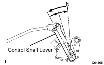
Move the shift lever to the N position and tighten the nut while lightly pushing the lever toward the R position.
- NOTICE:
- Do not push the shift lever too hard.
After adjustment, check that the shift lever moves smoothly and the shift lever and gear operate correctly.
| 17. INSPECT SHIFT LEVER POSITION |
When shifting from the P to R position with the engine switch on (IG) and the brake pedal depressed, make sure that the shift lever moves smoothly and moves correctly into the position.
Start the engine and make sure that the vehicle moves forward when shifting from the N to D position and moves rearward when shifting to the R position.
If operation cannot be done as specified, inspect the park/neutral position switch assembly and check the shift lever assembly installation condition.
| 18. CHECK FOR EXHAUST GAS LEAKS |