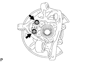
REMOVAL
Removal / installation
| 1. REMOVE REAR WHEEL |
| 2. SEPARATE REAR STABILIZER LINK ASSEMBLY |

Remove the bolt and nut, and separate the load sensing valve sensor bracket and stabilizer link assembly.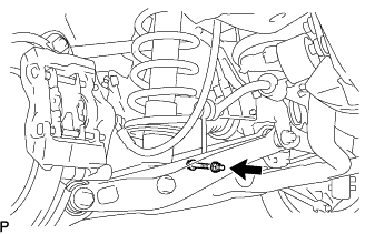

| 3. REMOVE REAR AXLE SHAFT NUT |
Using SST and a hammer, release the staked part of the axle shaft nut.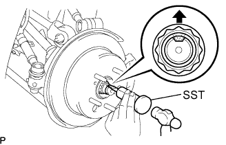
- SST
- 09930-00010
- NOTICE:
- Release the staked part of the nut completely, otherwise the screw of the drive shaft may be damaged.
Remove the rear axle shaft nut.
| 4. SEPARATE REAR DISC BRAKE CALIPER ASSEMBLY |
Remove the 2 bolts, and disconnect the rear disc brake caliper assembly.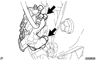
- NOTICE:
- Use wire or equivalent to prevent the brake caliper from hanging down by the flexible hose.
Remove the No.1 caliper plates from the brake caliper.
| 5. REMOVE REAR DISC |
Put matchmarks on the rear disc and the axle hub.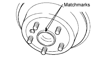
Remove the read disc.
| 6. SEPARATE REAR SPEED SENSOR |
Remove the 2 bolts, and separate the speed sensor from the axle carrier.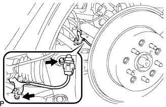
- NOTICE:
- Be careful not to damage the speed sensor.
- Prevent foreign matter from adhering to the speed sensor.
- Be careful not to damage the speed sensor.
| 7. REMOVE NO. 2 PARKING BRAKE SHOE RETURN SPRING |
Using SST, remove the No. 2 parking brake shoe return spring.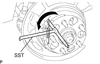
- SST
- 09703-30011
| 8. REMOVE NO. 1 PARKING BRAKE SHOE RETURN SPRING |
Using SST, remove the No. 1 parking brake shoe return spring.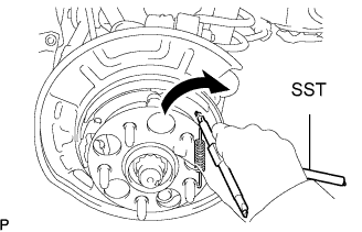
- SST
- 09703-30011
| 9. REMOVE PARKING BRAKE SHOE ADJUSTING SCREW SET |
Slide the parking brake shoe, and remove the parking brake shoe adjusting screw set.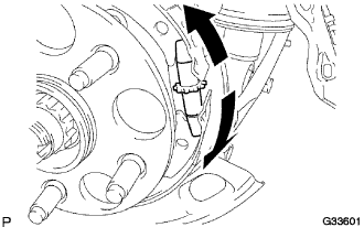
| 10. REMOVE NO. 2 PARKING BRAKE SHOE ASSEMBLY |
Using SST, remove the No. 1 shoe hold down spring cup, No. 1 compression spring and No. 1 shoe hold down spring pin.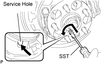
- SST
- 09718-00010
Remove the No. 2 parking brake shoe assembly.
- HINT:
- Use the service hole to retain the No. 1 hold down spring pin with your finger.
| 11. REMOVE NO. 1 PARKING BRAKE SHOE ASSEMBLY |
Using SST, remove the No. 1 shoe hold down spring cup, No. 1 compression spring and No. 1 shoe hold down spring pin.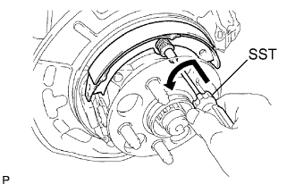
- SST
- 09718-00010
Remove the No. 1 parking brake shoe assembly.
- HINT:
- Use the service hole to retain the No. 1 hold down spring pin with your finger.
| 12. INSTALL PARKING BRAKE SHOE LEVER |
Remove the parking brake shoe lever.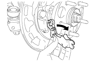
| 13. SEPARATE PARKING BRAKE CABLE ASSEMBLY |
Remove the 2 nuts, and separate the parking brake cable assembly from the rear axle carrier sub-assembly.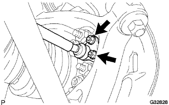
| 14. SEPARATE NO. 2 REAR UPPER CONTROL ARM ASSEMBLY |
Remove the nut from the No. 2 upper control arm assembly rear.
Using SST, separate the No. 2 upper control arm assembly rear from the rear axle carrier sub-assembly.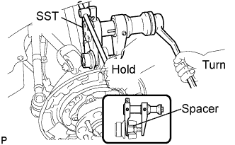
- SST
- 09628-00011
- NOTICE:
- Use caution not to damage the rear axle carrier because it is made of aluminum and may be damaged easily.
- Do not damage the ball joint dust cover.
- Make sure that the SST is securely positioned on the rear axle carrier spacer.
- If the rear axle carrier spacer has come off, replace the rear axle carrier with a new one.
- Make sure that the string of the SST is securely tied to the vehicle.
- Use caution not to damage the rear axle carrier because it is made of aluminum and may be damaged easily.
| 15. SEPARATE NO. 1 REAR UPPER CONTROL ARM ASSEMBLY |
Jack up the rear axle assembly so that the bolt on the No. 1 upper control arm assembly rear can be removed.
- HINT:
- Place a wooden block between the jack and rear axle carrier to prevent damage to the rear axle carrier.
Remove the bolt, washer and nut, and separate the No. 1 upper control arm assembly rear from the rear axle carrier sub-assembly.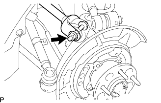
| 16. SEPARATE NO. 1 REAR SUSPENSION ARM ASSEMBLY |
Remove the bolt and nut, and separate the No. 1 rear suspension arm assembly from the rear axle carrier sub-assembly.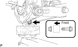
- NOTICE:
- Turn the bolt while holding the nut.
| 17. SEPARATE NO. 2 REAR SUSPENSION ARM ASSEMBLY |
Remove the bolt and nut, and separate the No. 2 rear suspension arm assembly from the rear axle carrier sub-assembly.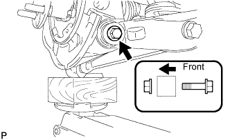
- NOTICE:
- Turn the bolt while holding the nut.
| 18. SEPARATE TOE CONTROL LINK SUB-ASSEMBLY |
Remove the nut from the toe control link sub-assembly.
Using SST, separate the toe control link sub-assembly from the rear axle carrier sub-assembly.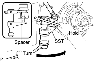
- SST
- 09628-00011
- NOTICE:
- Use caution not to damage the rear axle carrier because it is made of aluminum and may be damaged easily.
- Do not damage the ball joint dust cover.
- Make sure that the SST is securely positioned on the rear axle carrier spacer.
- If the rear axle carrier spacer has come off, replace the rear axle carrier with a new one.
- Make sure that the string of the SST is securely tied to the vehicle.
- Use caution not to damage the rear axle carrier because it is made of aluminum and may be damaged easily.
| 19. REMOVE REAR AXLE ASSEMBLY |
Using a plastic hammer, separate the drive shaft from the rear axle assembly.
- NOTICE:
- Be careful not to damage the boot.
- Use wire or equivalent to prevent the rear drive shaft assembly from hanging down.
- Be careful not to damage the boot.
| 20. REMOVE NO. 2 REAR WHEEL BEARING DUST DEFLECTOR |
Using a screwdriver, remove the No. 2 rear wheel bearing dust deflector from the rear axle carrier sub-assembly.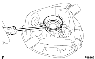
| 21. REMOVE REAR AXLE HUB AND BEARING ASSEMBLY |
Hold the axle hub and bearing assembly in a vise between aluminium plates.
- NOTICE:
- Do not overtighten the vise.
Remove the 4 bolts, axle hub and bearing assembly from the rear axle carrier sub-assembly.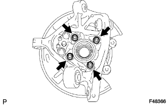
Remove the 2 nuts, parking brake anchor block, cable support bracket and parking brake plate.