INSTALLATION
Removal / installation
| 1. INSTALL REAR AXLE HUB AND BEARING ASSEMBLY |

Hold the axle hub and bearing assembly in a vise between aluminium plates.
- NOTICE:
- Do not overtighten the vise.
Install the parking brake anchor block, cable support bracket and parking brake plate with the 2 nuts.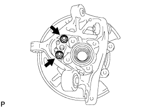

- Torque:
- 76 N*m{ 775 kgf*cm , 56 ft.*lbf }
Install the axle hub and bearing assembly to the rear axle carrier sub-assembly with the 4 bolts.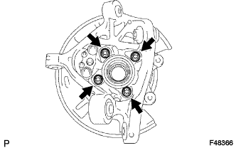
- Torque:
- 70 N*m{ 714 kgf*cm , 52 ft.*lbf }
| 2. INSTALL NO. 2 REAR WHEEL BEARING DUST DEFLECTOR |
Using SST and a hammer, install a new No. 2 rear wheel bearing dust deflector to the rear axle carrier sub-assembly.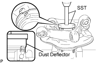
- SST
- 09951-01000
09950-70010 (09951-07150)
- HINT:
- Align the hole for the speed sensor in the No.2 rear wheel bearing dust deflector with the rear axle carrier sub-assembly.
| 3. INSTALL REAR AXLE ASSEMBLY |
Install the rear drive shaft assembly and rear axle assembly.
| 4. INSTALL NO. 2 REAR UPPER CONTROL ARM ASSEMBLY |
Install the No. 2 rear upper control arm assembly to the rear axle carrier sub-assembly with a new nut.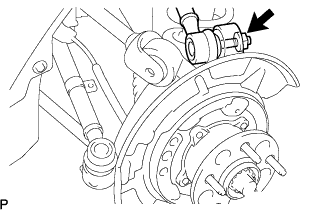
- Torque:
- 70 N*m{ 714 kgf*cm , 52 ft.*lbf }
| 5. TEMPORARILY TIGHTEN NO. 1 REAR UPPER CONTROL ARM ASSEMBLY |
Temporarily tighten the No. 1 rear upper control arm assembly to the rear axle carrier sub-assembly with the bolt, washer and nut.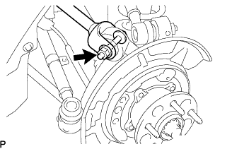
- HINT:
- Install the bolt from the rear side of the vehicle and lightly tighten the bolt.
| 6. TEMPORARILY TIGHTEN NO. 1 REAR SUSPENSION ARM ASSEMBLY |
Temporarily tighten the No. 1 rear suspension arm assembly to the rear axle carrier sub-assembly with the bolt and nut.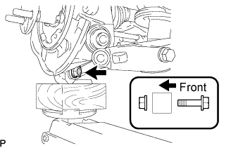
- HINT:
- Install the bolt from the rear side of the vehicle and lightly tighten the bolt.
| 7. TEMPORARILY TIGHTEN NO. 2 REAR SUSPENSION ARM ASSEMBLY |
Temporarily tighten the No. 2 rear suspension arm assembly to the rear axle carrier sub-assembly with the bolt and nut.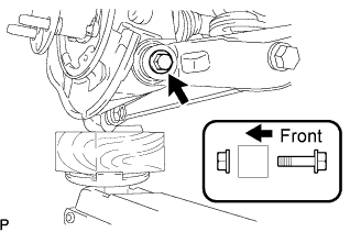
- HINT:
- Install the bolt from the rear side of the vehicle and lightly tighten the bolt.
| 8. INSTALL TOE CONTROL LINK SUB-ASSEMBLY |
Install the toe control link sub-assembly to the rear axle carrier sub-assembly with a new nut.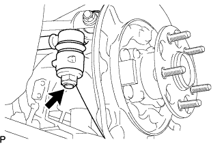
- Torque:
- 70 N*m{ 714 kgf*cm , 52 ft.*lbf }
| 9. INSTALL REAR STABILIZER LINK ASSEMBLY |
Install the stabilizer link assembly and the load sensing valve sensor bracket to the No. 2 rear suspension arm assembly with the bolt and nut.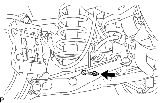
- Torque:
- 27 N*m{ 275 kgf*cm , 20 ft.*lbf }
| 10. INSTALL PARKING BRAKE CABLE ASSEMBLY |
Install the parking brake cable assembly to the rear axle carrier sub-assembly with the 2 nuts.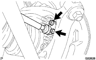
- Torque:
- 8.0 N*m{ 82 kgf*cm , 71 in.*lbf }
| 11. APPLY HIGH TEMPERATURE GREASE |
Apply a thin layer of high temperature grease to the area where the parking brake plate contacts the parking brake shoe (Click here).
| 12. INSTALL PARKING BRAKE SHOE LEVER |
Apply a thin layer of high temperature grease to the area where the parking brake shoe lever contacts the parking brake anchor block.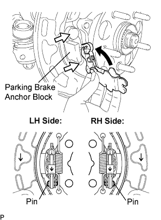
Install the parking brake shoe lever to the parking brake cable assembly.
- NOTICE:
- Take care to install the correct parking brake shoe lever because the direction of the pin is different between left and right.
| 13. INSTALL NO. 2 PARKING BRAKE SHOE ASSEMBLY |
Using SST, install the No. 2 parking brake shoe assembly with the No. 1 shoe hold down spring cup, No. 1 compression spring and No. 1 shoe hold down spring pin.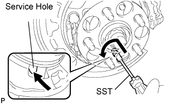
- SST
- 09718-00010
- HINT:
- Use the service hole to retain the No. 2 shoe hold down spring pin with your finger.
| 14. INSTALL NO. 1 PARKING BRAKE SHOE ASSEMBLY |
Using SST, install the No. 1 parking brake shoe assembly with the No. 1 shoe hold down spring cup, No. 1 compression spring and No. 1 shoe hold down spring pin.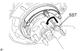
- SST
- 09718-00010
- HINT:
- Use the service hole to retain the No. 1 shoe hold down spring pin with your finger.
| 15. INSTALL PARKING BRAKE SHOE ADJUSTING SCREW SET |
Slide the parking brake shoe, and remove the parking brake shoe adjusting screw set.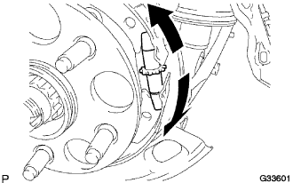
| 16. INSTALL NO. 2 PARKING BRAKE SHOE RETURN SPRING |
Using SST, install the No. 2 parking brake shoe assembly with the No. 1 shoe hold down spring cup, No. 1 compression spring and No. 1 shoe hold down spring pin.
- SST
- 09718-00010
- HINT:
- Use the service hole to retain the No. 2 shoe hold down spring pin with your finger.
| 17. INSTALL NO. 1 PARKING BRAKE SHOE RETURN SPRING |
Using SST, install the No. 1 parking brake shoe assembly with the No. 1 shoe hold down spring cup, No. 1 compression spring and No. 1 shoe hold down spring pin.
- SST
- 09718-00010
- HINT:
- Use the service hole to retain the No. 1 shoe hold down spring pin with your finger.
| 18. CHECK PARKING BRAKE INSTALLATION |
Make sure that all the parts are installed properly.
If necessary, reinstall properly.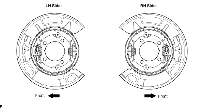
| 19. INSTALL REAR SPEED SENSOR |
Install the speed sensor to the rear axle carrier with the 2 bolts.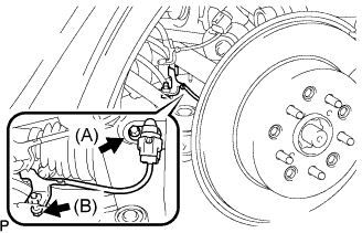
- Torque:
- Bolt (A):
- 8.5 N*m{ 87 kgf*cm , 75 in.*lbf }
- Bolt (B):
- 6.0 N*m{ 61 kgf*cm , 53 in.*lbf }
- NOTICE:
- Be careful not to damage the speed sensor.
- Prevent foreign matter from adhering to the speed sensor.
- Do not twist the sensor wire when installing the speed sensor.
- Be careful not to damage the speed sensor.
| 20. INSPECT REAR AXLE HUB BEARING FOR LOOSENESS |
Using a dial indicator, check for looseness near the center of the axle hub.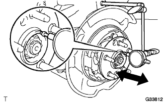
- Maximum:
- 0.05 mm (0.0020 in.)
- NOTICE:
- Ensure that the dial indicator is set perpendicular to the measurement surface.
| 21. INSPECT REAR AXLE HUB FOR RUNOUT |
Using a dial indicator, check for runout on the surface of the axle hub outside the hub bolt.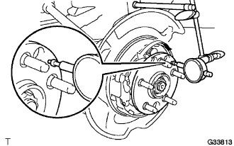
- Maximum:
- 0.05 mm (0.0020 in.)
- NOTICE:
- Ensure that the dial indicator is set perpendicular to the measurement surface.
| 22. INSTALL REAR DISC |
Aligning the matchmarks, install the rear disc.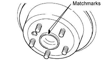
- HINT:
- When replacing the rear disc with a new one, select the installation position where the rear disc has the minimum runout.
| 23. ADJUST PARKING BRAKE SHOE CLEARANCE |
Temporarily install the hub nuts.
Remove the shoe adjusting hole plug.
Turn the shoe adjuster and expand the shoe until the disc locks.
Turn and contract the shoe adjuster until the disc can rotate smoothly.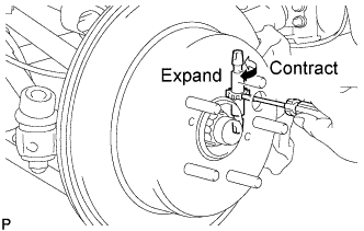
- Standard:
- Return 7 notches
Check that there is no brake drag against the shoe.
Install the shoe adjusting hole plug.
Remove the hub nuts.
| 24. INSTALL REAR DISC BRAKE CALIPER ASSEMBLY |
Install the rear disc brake caliper assembly and No. 1 caliper plates with the 2 bolts.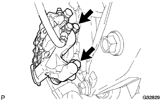
- Torque:
- 54 N*m{ 551 kgf*cm , 40 ft.*lbf }
- NOTICE:
- Do not twist the rear brake hose when installing the rear disc brake caliper.
- Make sure that there are no foreign objects or damage to the threads.
- Do not overtighten the bolts because the hub carrier is made of aluminum and may be damaged.
- Do not twist the rear brake hose when installing the rear disc brake caliper.
| 25. INSTALL REAR AXLE SHAFT NUT |
Using a chisel and a hammer, stake the axle shaft nut.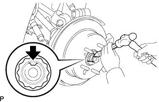
| 26. STABILIZE SUSPENSION |
Install the rear wheels.
Lower the vehicle to the ground. Bounce the vehicle up and down at the corners to stabilize the rear suspension.
Remove the rear wheels.
Jack up the axle carrier, with a wooden block placed between the jack and axle carrier, to apply a load to the suspension so that the rear drive shaft assembly becomes level.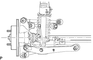
| 27. FULLY TIGHTEN NO. 1 REAR UPPER CONTROL ARM ASSEMBLY |
Fully tighten the No. 1 rear upper control arm assembly with the nut.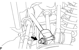
- Torque:
- 161 N*m{ 1,642 kgf*cm , 119 ft.*lbf }
| 28. FULLY TIGHTEN NO. 1 REAR SUSPENSION ARM ASSEMBLY |
Fully tighten the No. 1 rear suspension arm assembly with the bolt and nut.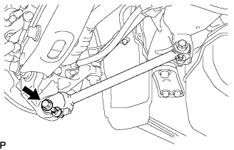
- Torque:
- 95 N*m{ 969 kgf*cm , 70 ft.*lbf }
- NOTICE:
- Turn the bolt while holding the nut.
| 29. FULLY TIGHTEN NO. 2 REAR SUSPENSION ARM ASSEMBLY |
Fully tighten the No. 2 rear suspension arm assembly with the bolt and nut.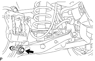
- Torque:
- 161 N*m{ 1,642 kgf*cm , 119 ft.*lbf }
- NOTICE:
- Turn the bolt while holding the nut.
| 30. INSTALL REAR WHEEL |
- Torque:
- 103 N*m{ 1,050 kgf*cm , 76 ft.*lbf }
| 31. INSPECT PARKING BRAKE PEDAL TRAVEL (for Automatic Transaxle) |
Fully depress the parking brake pedal and release it to engage the parking brake.
Depress the pedal to the floor again, and release it to disengage the parking brake.
Slowly depress the parking brake pedal to the floor, and count the number of clicks.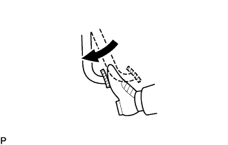
- Parking brake pedal travel:
- 7 to 9 notches at 300 N (31 kgf, 67.5 lbf)
| 32. ADJUST PARKING BRAKE PEDAL TRAVEL (for Automatic Transaxle) |
Depress the parking brake pedal. Hold the No. 1 wire adjusting nut using a wrench and loosen the lock nut.
Release the parking brake pedal.
Turn the No. 1 wire adjusting nut until the parking brake pedal travel meets the above specification.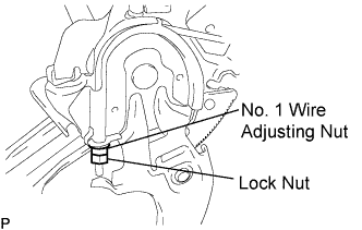
Hold the wire adjusting No. 1 nut using a wrench or equivalent tool and tighten the lock nut.
- Torque:
- 6.0 N*m{ 61 kgf*cm , 53 in.*lbf }
Count the number of clicks after depressing and releasing the parking brake pedal 3 or 4 times.
Check whether the parking brake drags or not.
When operating the parking brake pedal, check that the parking brake indicator light comes on.
| 33. INSPECT PARKING BRAKE LEVER TRAVEL (for Manual Transmission) |
Pull firmly on the parking brake lever.
Release the parking brake lock, and return the parking brake lever to its off position.
Slowly pull the parking brake lever all the way up, and count the number of clicks.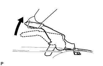
- Parking brake lever travel:
- 4 to 6 notches at 200 N (20 kgf, 45 lbf)
| 34. ADJUST PARKING BRAKE LEVER TRAVEL (for Manual Transmission) |
Depress the parking brake lever. Hold the No. 1 wire adjusting nut using a wrench and loosen the lock nut.
Release the parking brake lever.
Turn the No. 1 wire adjusting nut until the parking brake lever travel meets the above specification.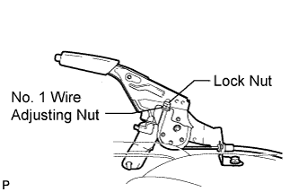
Hold the No. 1 wire adjusting nut using a wrench or equivalent tool and tighten the lock nut.
- Torque:
- 6.0 N*m{ 61 kgf*cm , 53 in.*lbf }
Count the number of clicks after depressing and releasing the parking brake lever 3 or 4 times.
Check whether the parking brake drags or not.
When operating the parking brake lever, check that the parking brake indicator light comes on.
| 35. INSPECT AND ADJUST REAR WHEEL ALIGNMENT |
| 36. CHECK ABS SPEED SENSOR SIGNAL |