REMOVAL
Removal / installation
| 1. REMOVE REAR WHEEL |
| 2. REMOVE NO. 2 FLOOR UNDER COVER |
| 3. REMOVE NO. 1 FLOOR UNDER COVER |
| 4. REMOVE NO. 2 DIFFERENTIAL SUPPORT PROTECTOR |

Remove the 2 nuts and No. 2 differential support protector from the suspension member brace.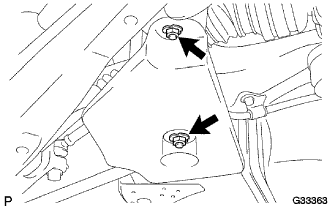

| 5. REMOVE NO. 1 DIFFERENTIAL SUPPORT PROTECTOR |
- HINT:
- Removal procedure of the No.1 differential support protector is the same as that of the No.2 differential support protector.
| 6. DRAIN DIFFERENTIAL OIL |
Using a hexagon wrench (10 mm), remove the differential filler plug and gasket.
Using a hexagon wrench (10 mm), remove the differential drain plug and gasket, and drain the oil.
| 7. REMOVE REAR STABILIZER LINK ASSEMBLY LH |
Remove the nut, and separate the rear stabilizer link assembly LH from the rear stabilizer bar. (A)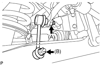
- NOTICE:
- Be sure to hold the stud bolt using a hexagon wrench 6 in order to prevent the bolt from turning.
Remove the bolt, nut, and the stabilizer link assembly LH. (B)
| 8. REMOVE REAR STABILIZER LINK ASSEMBLY RH |
- HINT:
- Removal procedure of the RH side is the same as that of the LH side.
| 9. REMOVE STABILIZER BAR REAR |
Remove the 4 bolts, 2 stabilizer brackets, 2 rear stabilizer bushing, and rear stabilizer bar.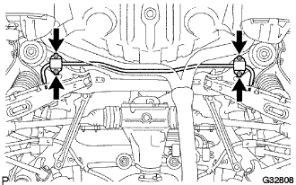
| 10. REMOVE REAR NO. 1 FLOOR PANEL BRACE |
Remove the 4 bolts and rear No. 1 floor panel brace.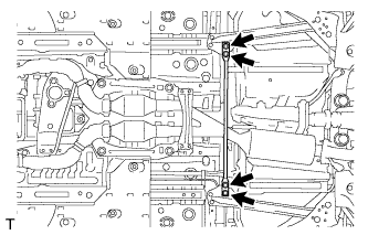
| 11. REMOVE FRONT CENTER FLOOR BRACE |
Remove the 4 bolts and front center floor brace .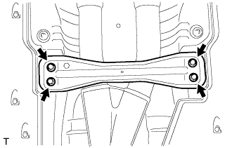
| 12. DISCONNECT HEATED OXYGEN SENSOR |
Remove the grommets of the heated oxygen sensors (BANK 1, BANK 2).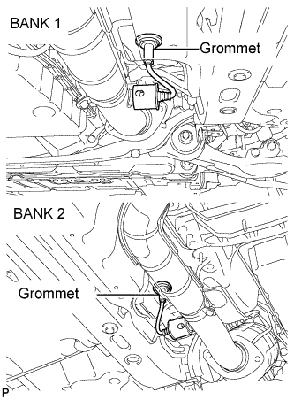
Using the SST, remove a oxygen sensors (BANK 1, BANK 2).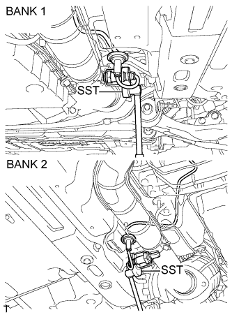
- SST
- 09224-00010
| 13. REMOVE FRONT EXHAUST PIPE ASSEMBLY |
Remove the 4 bolts and 4 nuts.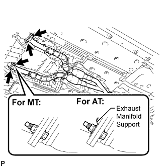
Remove the 2 bolts and 2 compression springs from the tail exhaust pipe assembly.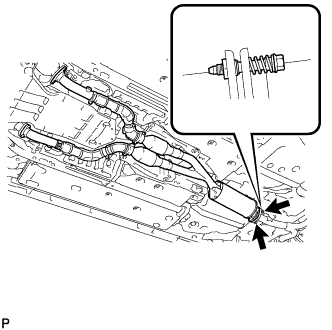
Remove the front exhaust pipe assembly and 3 gaskets.
| 14. REMOVE TAIL EXHAUST PIPE ASSEMBLY |
Disconnect the 6 exhaust pipe supports to remove the tail exhaust pipe assembly.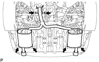
| 15. REMOVE AIR GUIDE PLATE OUTSIDE RH |
Remove the 4 nuts and outside air guide plate RH.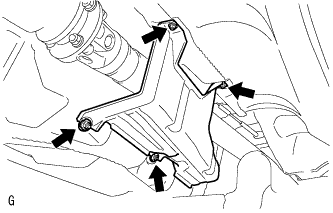
| 16. REMOVE FRONT NO. 1 FLOOR HEAT INSULATOR |
Remove the 4 nuts and front No. 1 floor heat insulator.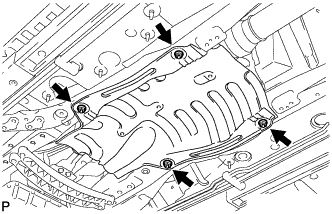
| 17. REMOVE PROPELLER SHAFT WITH CENTER BEARING ASSEMBLY |
Put matchmarks on both flanges.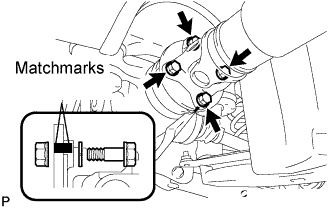
Remove the 4 nuts, bolts and washers.
- HINT:
- If the flange connection is hard to separate, temporarily tighten one nut only and evenly tap the flange with a brass bar and hammer to separate the propeller shaft assembly from the differential companion flange.
Remove the 2 bolts and 2 center support bearing washers. (for automatic transmission)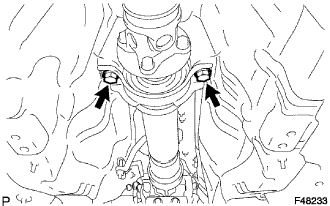
Remove the 2 bolts, 2 center support bearing washers and 2 center support bearing dampers. (for manual transmission)
Separate the center support bearing.
Insert SST in the transmission to prevent oil leakage.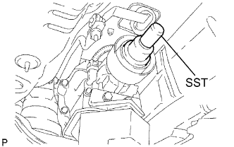
- SST
- 09325-40010
- NOTICE:
- Be careful not to damage the oil seal.
| 18. REMOVE REAR SUSPENSION MEMBER BRACE LH |
Remove the 2 bolts and rear suspension member brace LH.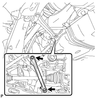
| 19. REMOVE REAR SUSPENSION MEMBER BRACE RH |
- HINT:
- Removal procedure of the RH side is the same as that of the LH side.
| 20. SEPARATE NO. 3 PARKING BRAKE CABLE ASSEMBLY |
Remove the 3 bolts and disengage the 2 clamps and No. 3 parking brake cable assembly LH.
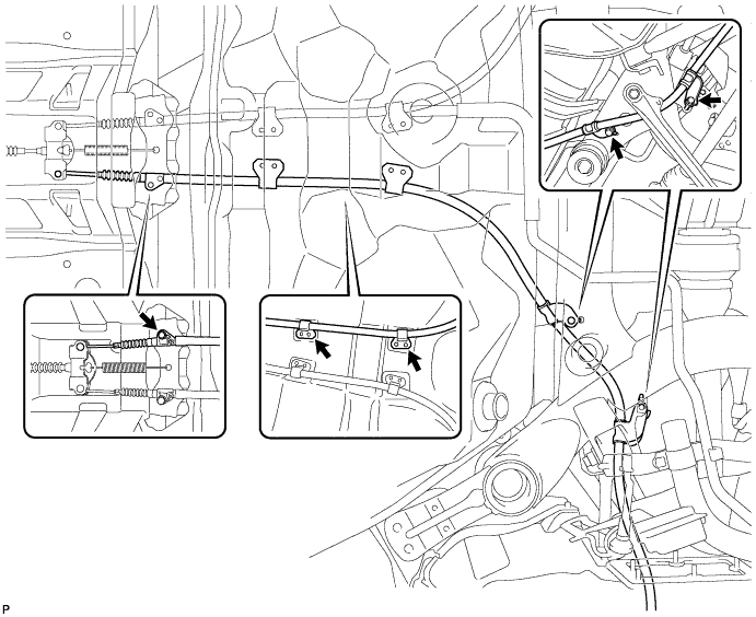
Separate the No. 3 parking brake cable assembly LH from the parking brake equalizer.
| 21. SEPARATE NO. 2 PARKING BRAKE CABLE ASSEMBLY |
- HINT:
- Removal procedure of the No.2 parking brake cable assembly is the same as that of the No.3 parking brake cable assembly.
| 22. REMOVE REAR AXLE SHAFT NUT LH |
Using SST and a hammer, release the staked part of the axle shaft nut.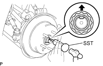
- SST
- 09930-00010
- NOTICE:
- Release the staked part of the nut completely, otherwise the screw of the drive shaft may be damaged.
Remove the rear axle shaft nut.
| 23. REMOVE REAR AXLE SHAFT NUT RH |
- HINT:
- Removal procedure of the RH side is the same as that of the LH side.
| 24. SEPARATE REAR DISC BRAKE CALIPER ASSEMBLY LH |
Remove the 2 bolts, and disconnect the rear disc brake caliper assembly.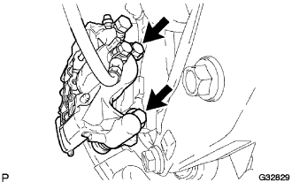
- NOTICE:
- Use wire or equivalent to prevent the brake caliper from hanging down by the flexible hose.
Remove the No.1 caliper plates from the brake caliper.
| 25. SEPARATE REAR DISC BRAKE CALIPER ASSEMBLY RH |
- HINT:
- Removal procedure of the RH side is the same as that of the LH side.
| 26. SEPARATE REAR SHOCK ABSORBER WITH COIL SPRING LH |
Remove the bolt and nut, and separate the rear shock absorber with coil spring from the rear No. 2 suspension arm assembly.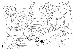
| 27. SEPARATE REAR SHOCK ABSORBER WITH COIL SPRING RH |
- HINT:
- Removal procedure of the RH side is the same as that of the LH side.
| 28. SEPARATE REAR SPEED SENSOR LH |
Remove the 2 bolts, and separate the speed sensor from the axle carrier.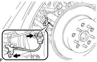
- NOTICE:
- Be careful not to damage the speed sensor.
- Prevent foreign matter from adhering to the speed sensor.
- Be careful not to damage the speed sensor.
| 29. SEPARATE REAR SPEED SENSOR RH |
- HINT:
- Removal procedure of the RH side is the same as that of the LH side.
| 30. SEPARATE NO. 2 REAR UPPER CONTROL ARM ASSEMBLY LH |
Remove the nut from the No. 2 upper control arm assembly rear.
Using SST, separate the No. 2 upper control arm assembly rear from the rear axle carrier sub-assembly.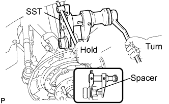
- SST
- 09628-00011
- NOTICE:
- Use caution not to damage the rear axle carrier because it is made of aluminum and may be damaged easily.
- Do not damage the ball joint dust cover.
- Make sure that the SST is securely positioned on the rear axle carrier spacer.
- If the rear axle carrier spacer has come off, replace the rear axle carrier with a new one.
- Make sure that the string of the SST is securely tied to the vehicle.
- Use caution not to damage the rear axle carrier because it is made of aluminum and may be damaged easily.
| 31. SEPARATE NO. 2 REAR UPPER CONTROL ARM ASSEMBLY RH |
- HINT:
- Removal procedure of the RH side is the same as that of the LH side.
| 32. SEPARATE NO. 1 REAR UPPER CONTROL ARM ASSEMBLY LH |
Jack up the rear axle assembly so that the bolt on the No. 1 upper control arm assembly rear can be removed.
- HINT:
- Place a wooden block between the jack and rear axle carrier to prevent damage to the rear axle carrier.
Remove the bolt, washer and nut, and separate the No. 1 upper control arm assembly rear from the rear axle carrier sub-assembly.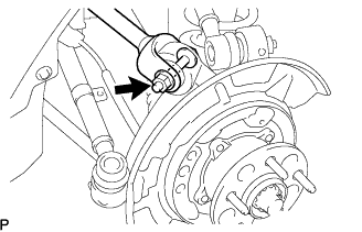
| 33. SEPARATE NO. 1 REAR UPPER CONTROL ARM ASSEMBLY RH |
- HINT:
- Removal procedure of the RH side is the same as that of the LH side.
| 34. SEPARATE NO. 1 REAR SUSPENSION ARM ASSEMBLY LH |
Remove the bolt and nut, and separate the No. 1 rear suspension arm assembly from the rear axle carrier sub-assembly.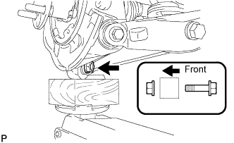
- NOTICE:
- Turn the bolt while holding the nut.
| 35. SEPARATE NO. 1 REAR SUSPENSION ARM ASSEMBLY RH |
- HINT:
- Removal procedure of the RH side is the same as that of the LH side.
| 36. SEPARATE NO. 2 REAR SUSPENSION ARM ASSEMBLY LH |
Remove the bolt and nut, and separate the No. 2 rear suspension arm assembly from the rear axle carrier sub-assembly.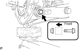
- NOTICE:
- Turn the bolt while holding the nut.
| 37. SEPARATE NO. 2 REAR SUSPENSION ARM ASSEMBLY RH |
- HINT:
- Removal procedure of the RH side is the same as that of the LH side.
| 38. SEPARATE TOE CONTROL LINK SUB-ASSEMBLY LH |
Remove the nut from the toe control link sub-assembly.
Using SST, separate the toe control link sub-assembly from the rear axle carrier sub-assembly.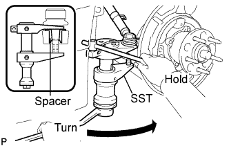
- SST
- 09628-00011
- NOTICE:
- Use caution not to damage the rear axle carrier because it is made of aluminum and may be damaged easily.
- Do not damage the ball joint dust cover.
- Make sure that the SST is securely positioned on the rear axle carrier spacer.
- If the rear axle carrier spacer has come off, replace the rear axle carrier with a new one.
- Make sure that the string of the SST is securely tied to the vehicle.
- Use caution not to damage the rear axle carrier because it is made of aluminum and may be damaged easily.
| 39. SEPARATE TOE CONTROL LINK SUB-ASSEMBLY RH |
- HINT:
- Removal procedure of the RH side is the same as that of the LH side.
| 40. REMOVE REAR AXLE ASSEMBLY LH |
Using a plastic hammer, separate the drive shaft from the rear axle assembly.
- NOTICE:
- Be careful not to damage the boot.
- Use wire or equivalent to prevent the rear drive shaft assembly from hanging down.
- Be careful not to damage the boot.
| 41. REMOVE REAR AXLE ASSEMBLY RH |
- HINT:
- Removal procedure of the RH side is the same as that of the LH side.
| 42. REMOVE REAR DRIVE SHAFT ASSEMBLY LH |
Using SST, remove the rear drive shaft assembly.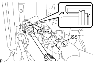
- SST
- 09520-01010
09520-24010 (09520-32040)
- NOTICE:
- Be careful not to damage the oil seal, inboard joint boot and drive shaft dust cover.
- Be careful not to drop the drive shaft assembly.
- Be careful not to damage the oil seal, inboard joint boot and drive shaft dust cover.
| 43. REMOVE REAR DRIVE SHAFT ASSEMBLY RH |
- HINT:
- Removal procedure of the RH side is the same as that of the LH side.
| 44. DISCONNECT REAR HEIGHT CONTROL SENSOR SUB-ASSEMBLY |
Disconnect the height control sensor connector.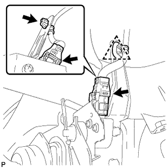
Remove the clamp from the rear suspension member.
| 45. REMOVE REAR SUSPENSION MEMBER BRACE LOWER LH |
Remove the 4 bolts and suspension member brace lower LH.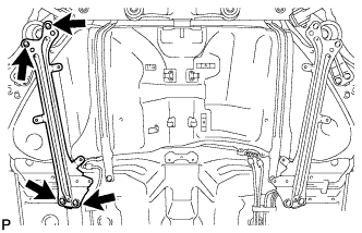
| 46. REMOVE REAR SUSPENSION MEMBER BRACE LOWER RH |
Remove the 4 bolts and suspension member brace lower RH.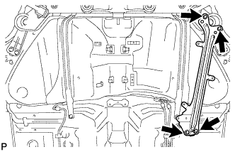
| 47. REMOVE REAR SUSPENSION MEMBER SUB-ASSEMBLY |
Support the rear suspension member with a jack.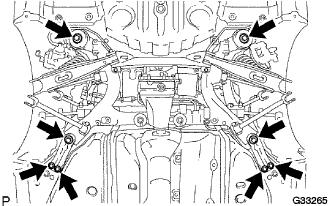
- HINT:
- Remove the rear suspension member along with the differential carrier assembly rear.
Remove the 8 bolts, 2 rear suspension member stoppers, 2 differential support member stoppers and rear suspension member stopper lowers from the rear suspension member.
Lower the jack slowly and remove the rear suspension member with the differential carrier assembly rear.
| 48. REMOVE REAR DIFFERENTIAL CARRIER ASSEMBLY |
Using a hexagon wrench (12 mm), remove the 3 bolts (A).
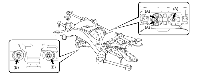
Remove the 2 bolts (B), 2 rear upper differential mount stoppers, 2 rear lower differential mount stoppers and rear differential carrier assembly.